MRWA Supplement to Austroads Guide to Road Design - Part 3 - Geometric Design
Table of Contents
- 1. Introduction
- 2. Fundamental Considerations
- 3. Speed Parameters
- 4. Cross Section
- 5. Sight Distance
- 6. Coordination of Horiztonal and Vertical Alignment
- 7. Horizontal Alignment
- 8. Vertical Alignment
- 9. Auxiliary Lanes
- 10. Bridge Considerations
- 11. Appendix
- Appendix A Extended Design Domain (EDD) for Geometric Road Design
- Appendix B Emergency Aircraft Runway Strips
- Appendix C Speed Parameter Terminology
- Appendix D Example Calculation of the Operating Speed Model
- Appendix E Narrow Median Treatments with Wire Rope Safety Barrier
- Appendix F Guidance for Wide Centreline Treatments
- Appendix G Flow Charts and Table for Determining Stopping Sight Distance Requirements for Curves with Barriers
- Appendix H Theory of Movement in a Circular Path
- Appendix I Reverse Curves
- Appendix J Transition Curves (sprials)
- Appendix K Vertical Curve Curvature Formulae
- Appendix L Policy and Guidelines for Overtaking Lanes
This Supplement has been developed to be read in conjunction with the Austroads Guide to Road Design (GRD) Part 3: Geometric Design (2016), a copy of which can be purchased via the Austroads website.
In Western Australia, Main Roads' policies, guidelines and standards take precedence over Austroads Guides and Standards Australia Standards. National Guides and Standards take precedence over International Guides and Standards, unless specifically stated otherwise.This Supplement has the same structure as the equivalent Austroads Guide and only additional requirements, clarifications, or practices different from Austroads appear. Where appropriate, this Supplement may also contain additional sections and figures not covered by Austroads, but the numbering sequence found in the Austroads Guide remains. Figures and tables in this Supplement replace those with the same figure or table number in the equivalent Austroads Guide.
General Standards and Application
The purpose of this document is to detail Main Roads' standards for the geometric design of sealed roads in Western Australia and to provide practical guidelines for the application of these standards
All road design projects should have the following primary design objectives:
- Maximise safety.
- Minimise costs associated with construction, maintenance and use of the route.
- Minimise adverse impacts and enhance the environment where possible.
- Maximise operational efficiency - the ability to carry the required volume and mix of traffic at a speed acceptable to all road users.
- Take into account the views of the public including local residents, businesses, community groups and road users.
- Integrate visually with the surrounding environment.
- Consider the planned ultimate layout (road and adjacent developments) in the vicinity of the works and ensure that it can be accommodated with a minimum of reconstruction in the future.
- Maximise opportunities to cater for the needs of all road user groups.
1. Introduction
1.1 Purpose
For guidance on the design of unsealed roads refer to the "ARRB Unsealed Roads Manual; Guidelines to Good Practice - March 2009 edition".
1.3 Design Criteria in Part 3
Minimum standards are to be avoided except where absolutely critical to achieving the most suitable and safe outcome. Generally, if a minimum is used for any particular design element it becomes necessary to avoid using a minimum value for any other element on that particular segment or immediately adjacent road section. This is necessary to allow an appropriate factor of safety to road users.
The Designer is responsible for the preparation of documentation that correctly represents the design as outlined in the Design and Drawing Presentation guidelines. The Project Manager will arrange independent design reviews and audits to ensure that the design solution meets its primary objectives.
Where a minimum design standard is being considered, the Designer is required in the first instance to apply the Desirable Minimum value. Should that result in a solution that is not technically feasible or is unreasonably cost prohibitive, the Designer may adopt an Absolute Minimum as outlined in relevant Austroads Guides. These minimums are contained in the Normal Design Domain.
To go below an Absolute Minimum value is to go beyond the Normal Design Domain and into the Extended Design Domain (EDD) as explained in detail in Austroads GRD Part 2: Design Considerations (2015) and Appendix A in GRD Part 3 (2016). To apply a value outside the Normal Design Domain, a comprehensive risk assessment that fully justifies the use of that value must be submitted to the Manager Road & Traffic Engineering (MRTE). Acceptance of a design solution that utilises an EDD value is subject to the written approval of the MRTE.
2. Fundamental Considerations
2.2.7 Design Vehicle
More detailed information for Oversize and High Wide Loads can be obtained from Heavy Vehicle Services.
3. Speed Parameters
3.3 Operating Speeds on Urban Roads
Main Roads practice is to use a design speed that is 10km/h above the legal or posted speed limit for the design of urban roads.
3.4 Operating Speeds on Rural Roads
Where the operating speed of a rural road is not determined using the Operating Speed Model then Main Roads practice is to use a design speed that is 10km/h above the legal or posted speed limit for the design of rural roads to a maximum of 110km/h. For example, where the posted speed limit is to be 100km/h then the design speed is 110km/h.
Additional speed data can be obtained from local traffic classifiers, if not already available. The reader should check with the Asset & Geospatial Information Branch.
On sections of rural road that are also designed as emergency landing strips a higher design speed is required. Designers should refer to the Emergency Landing Strips guideline for further details.
3.8 Operating Speeds for Temporary Works (including sidetracks)
Designers should refer to the Temporary Alignments in Urban Areas guideline for further details associated with temporary works.
4. Cross Section
4.1A Seal and Shoulder Widths Across the State Road Network
Background
In January 2015, in the interest of applying consistent seal and formation widths across the rural road network in WA, “2031” seal and formation widths were developed based on a 20-year growth rate applied to a modified version of Table 4.5 in Section 4.2.6 based on Passenger Car Units (PCUs) per day rather than vehicles per day. The nominated cross-sections were confirmed with each Regional Manager and were presented in tabulated and colour-coded map format. Since then, the development of the Safe System approach to road safety has highlighted the need to optimise the cross sections from a road safety point of view.
Single Vehicle lane departure (run-off road, head-on) crashes in the rural high-speed state roads are the largest contributor to death and serious injuries on this part of the state network (69%). The annual cost of this trauma is $900M, which is a significant burden on the community both emotionally and financially. It is also recognised that 68% of Killed and Serious Injury (KSI) crashes are not due to deliberate violators of the traffic laws.
Evidence has proven there are a number of treatments which may be applied to greatly reduce these crashes from occurring. Sealing shoulders and installing Audible Edge lines have shown to substantially reduce the chance of these crash types by between 43% - 67% depending on the existing carriageway formation.
Methodology
The Road & Traffic Engineering and Road Safety Branches within the Planning and Technical Services Directorate developed a methodology to optimise the safety performance by modifying the carriageways for the rural high-speed network. The variations tested are as below.
- Do nothing case
- “2031” cross section based on Austroads requirements (previous approach)
- “2031” cross section based on the optimised Austroads Option (by fully sealing the shoulders of above)
- Low Cost Option (fulling sealing the shoulders of the existing formation – i.e. no widening of carriageway)
In addition to cross-sectional changes, a one metre wide median treatment with audible centre-lines was assessed on high volume heavy vehicle routes and routes that already exhibit a high number of head-on crashes. These routes include:
- Great Eastern Hwy (Metro boundary to Northam)
- Great Northern Hwy (Muchea- Wubin)
- South Western Hwy (Metropolitan Boundary - Donnybrook)
- Coalfields Hwy
- Bussell Hwy (Vasse - Margaret River)
- Toodyay Rd (Metro boundary to Toodyay)
- North West Coastal Hwy (Karratha- Roebourne)
The assessment utilised current research (Austroads, ARRB, C-MARC, NZTA, ANRAM) to determine Crash Modification Factors (CMF) to predict the reduction in KSI Iane departure crashes that are either Head-On, Hit Object or Roll-Over in nature. These types of crashes are the only ones that are likely to be influenced by a change in cross section. A summary of the assessment is shown in Table 1.1 below.
|
Scenario |
Based on 2031traffic |
Based on unit rates |
Based on existing formation |
NPV savings ($000,000) |
BCR |
|
|
Percentage reduction in KSIs |
Number - Reduction in KSI I pa |
Estimated Expenditure ($ 000,000) |
Formation widening reqd. (km) |
|||
|
Do nothing case |
+14% |
+35 |
0 |
0 |
-425 |
0 |
|
Austroads Cross Sections |
12% |
31 |
2,950 |
9860km |
-994 |
0.30 |
|
Low Cost Option |
61% |
122 |
872 |
0 |
1,278 |
4.05 |
|
Optimised Austroads Option |
62% |
126 |
3,148 |
9860km |
237 |
1.14 |
Notes: 1.All based on 2031forecast traffic growth (modelling data).
Table 1.1: Economic Summary of Various Scenarios
Route Strategies
It is important from a road user perspective to apply consistent seal and formation widths across the rural road network. This standardisation is included in the Route and Link Strategies developed by the Network Management Branch. The objective of a Route Strategy is to provide for the development of an agreed corporate Route Vision and Strategy aligned to specific Route Development and Management plans for rural routes in the road network. While a Route Strategy focuses on the long-term development of a route, it necessarily also needs to consider medium and short-term requirements.
2031 Cross Section
In the medium term, the design criteria described in this supplement, Section 4.2.6 (incorporating a 15 year growth rate to 2031) has been applied to identify a “2031” formation width for each of the rural road links. The seal width for each section has been determined by focussing on single vehicle lane departure crashes and optimising the cross-section to reduce the number of KSI crashes to meet the required target value. Consistency between adjacent road sections is also checked.
The widths are not intended to demonstrate the adequacy or inadequacy of the existing seal and formation widths. The nominated cross sections have been confirmed with each Regional Manager. The information is provided in the following colour coded maps for each region or may also be sourced through the Integrated Mapping System (IMS) by searching in the Layer Name catalogue under “Network” for “Seal & Pavement Widths 2031”.
- Seal & Pavement Widths 2031 - Kimberley Region
- Seal & Pavement Widths 2031 - Pilbara Region
- Seal & Pavement Widths 2031 - Mid-West - Gascoyne Region
- Seal & Pavement Widths 2031 - Wheatbelt Region
- Seal & Pavement Widths 2031 - Goldfields - Esperance Region
- Seal & Pavement Widths 2031 - South - West Region
- Seal & Pavement Widths 2031 - Great Southern Region
- Seal & Pavement Widths 2031 - South - West Area
- Seal & Pavement Widths 2031 - Western Australia
These cross sections are to be applied when single carriageway road upgrades are proposed, unless formal approval for an alternative cross section (eg. a low cost cross section) has been received from the relevant Executive Director or is in accordance with an approved route or link strategy. Note that these seal and formation widths do not apply where dual carriageway is required. For guidance associated with rural bridge widths refer to Section 11 of the Bridge Branch Design Information Manual.
Low Cost Cross Section
A low cost option was developed based on optimising the existing formation, predominantly by sealing the unsealed shoulders. As indicated in Table 1.1, this is expected to give a good benefit to cost ratio. The low cost option cross sections are provided in the following colour coded maps for each region or may also be sourced through the Integrated Mapping System (IMS) by searching in the Layer Name catalogue under “Network” for “Low Cost Seal & Pavement Widths”.
- Low Cost Seal & Pavement Widths - Kimberley Region
- Low Cost Seal & Pavement Widths - Pilbara Region
- Low Cost Seal & Pavement Widths - Mid-West - Gascoyne Region
- Low Cost Seal & Pavement Widths - Wheatbelt Region
- Low Cost Seal & Pavement Widths - Goldfields - Esperance Region
- Low Cost Seal & Pavement Widths - South - West Region
- Low Cost Seal & Pavement Widths - Great Southern Region
- Low Cost Seal & Pavement Widths - South - West Area
- Low Cost Seal & Pavement Widths - Western Australia
These cross sections are only to be applied when the available funding is insufficient to develop the “2031” cross section or where the funding source is specifically targeting a “low cost” option. It is important that consistency between adjacent road sections is maintained unless a natural transition occurs through a major intersection or townsite. The use of this option requires approval of the relevant Executive Director unless it is in accordance with an approved route or link strategy.
For ease of assessment, a Table showing the required “Low Cost” and “2031” Cross Sections for each Road has also been developed.
Freeway Cross Sections
The following typical cross sections outline a number of “ultimate” layouts, and demonstrate how intermediate stages can nest with the long term (All Lane Running) solution. Note that in each case, the ultimate is based on the premise of fully functioning “managed freeway” operation. Until then the outer shoulder is required for safety, and to facilitate subsequent traffic management during construction activities associated with staged widening.
In order to minimise subsequent relocation of services and other infrastructure, and to avoid later land acquisition, the outer edges of the cross section should be defined at the outset, allowing the future widening to occur into the median. This is especially important at interchanges to ensure that there is no need to relocate / modify ramps, drainage, lighting, etc as part of any widening activity. This approach also facilitates traffic management during the construction of additional lanes.
With the wider median associated with an interim stage, wire rope barrier is likely to be suitable as there will be adequate displacement / deflection width behind the fence. For the ultimate cross section however, a concrete barrier is expected to be required due to limited space behind the barrier. In some instances it may be appropriate to have a median comprising a concrete barrier alone.
In determining the ultimate width of median, consideration must be given to all facilities that may need to reside in this space. These may include the necessity to accommodate bridge piers; managed freeway or other gantries; drainage in areas of freeway superelevation; lighting; and/or future public transport infrastructure. In these circumstances, the ongoing maintenance requirements of all such infrastructure must be understood, with appropriate servicing procedures embedded in guidelines for future application. In cases of freeway superelevation, the flow width associated with drainage runoff should be taken into account to ensure that flow against a concrete barrier does not detrimentally affect friction requirements in the adjacent traffic lane.
Where the outer edge of pavement is kerbed, the width of drainage flow path must be taken into account to minimise the likelihood of aquaplaning in the kerbside lane.
The ultimate width of median shoulder also needs to address the sight distance constraints that may occur around horizontal geometry when a concrete barrier is in place. The absolute minimum sight distance that can be applied is that associated with enabling drivers to see the tail/stop lights of vehicles ahead, in order to minimise the risk of tail end crashes. In particular, refer to Section 5.5 of the Austroads Guide to Road Design Part 3 (2016).
Emergency Stopping Bays will be a requirement with All Lane Running solutions, and the locations, configuration and spacing of these should be identified in the first stage.
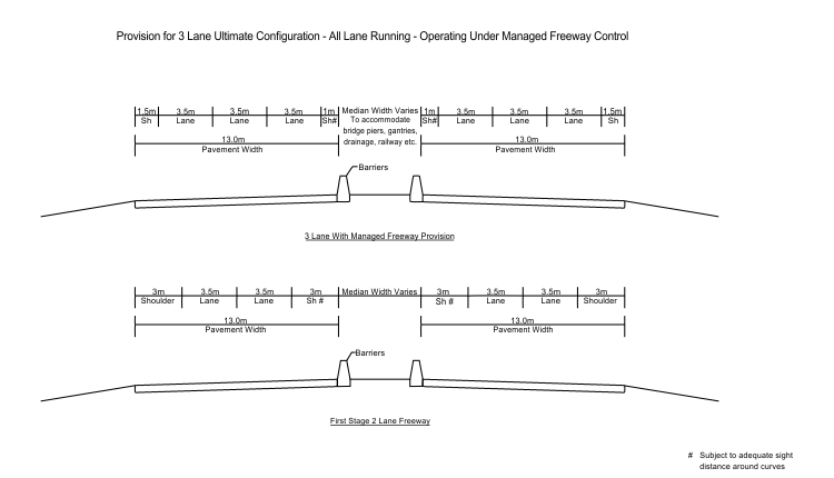 Figure 1.3: Provision for 3 lane Ultimate Configuration
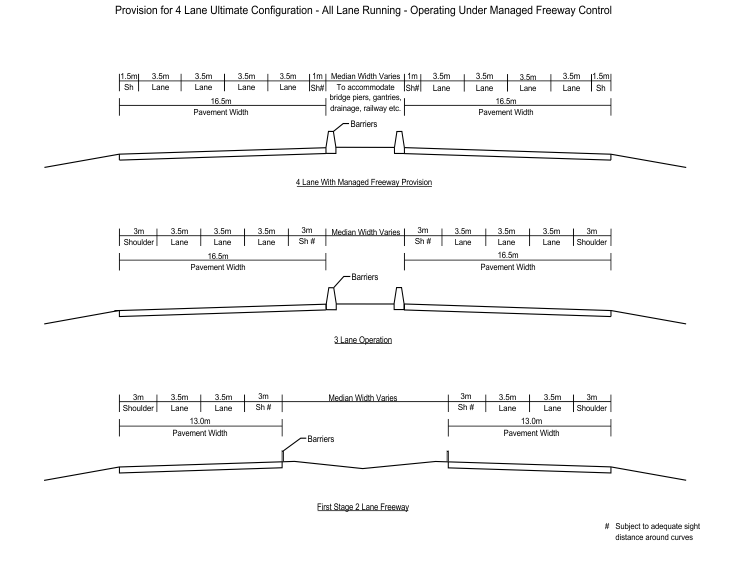
Figure 1.4: Provision for 4 lane Ultimate Configuration
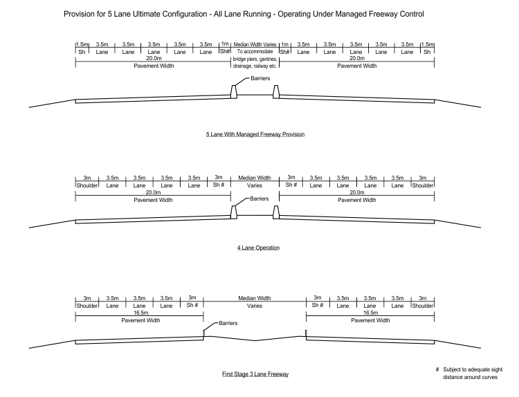
Figure 1.5: Provision for 5 lane Ultimate Configuration
4.1 General
The Designer should ensure that the use of the available space within the road reserve is balanced to achieve the fundamental design objectives when determining the cross section. Refer also to Seal and Shoulder Widths outlined in Section 4.1A above.
The width and crossfall of traffic lanes and shoulders are based on traffic needs and drainage requirements. The form of the remainder of the cross section, namely the batter slopes of embankments and cuttings, depends on the type of material to be placed or excavated, safety and environmental factors and the importance of the road.
For typical cross section terminology, refer to Figure 4.2 below and the Main Roads Glossary of Technical Terms guideline.
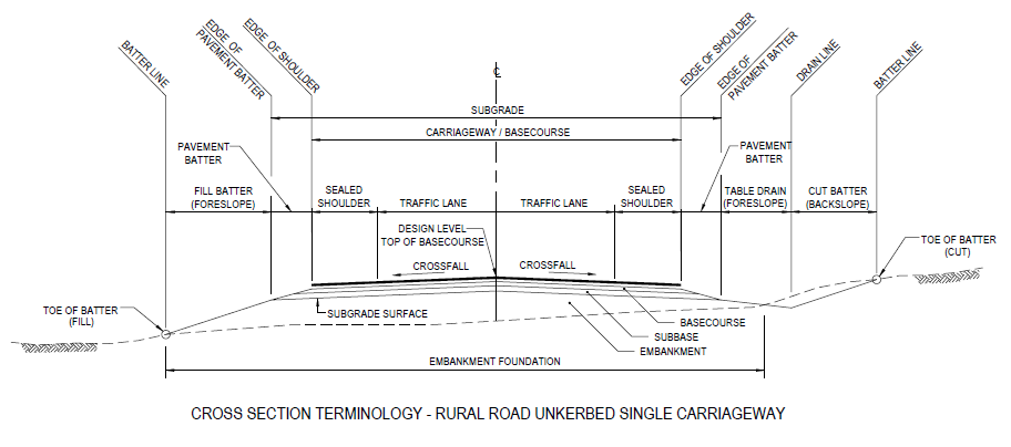
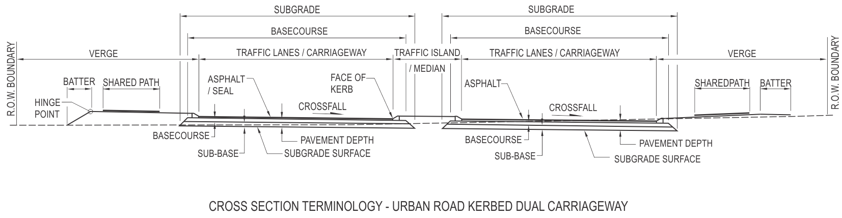
Figure 4.2: Typical Cross Section Terminology – Rural and Urban Roads
4.2.5 Urban Road Widths
Where site constraints preclude the use of the desirable standard width, consideration may be given to reducing the traffic lane width to 3.3 m, subject to the approval of the MRTE.
Where a section of road is part of a RAV route, the minimum lane width should be in accordance with the appendices in the document “Standard Restricted Access Vehicle Route Assessment Guidelines.
In relation to Austroads Table 4.3 urban arterial road widths note that in Western Australia the minimum width of a single kerbside lane suitable for use in a left turn slip lane, or two lane two way divided road with a raised median, is 6.0m (desirable) or 5.5m (absolute minimum). Delete Notes 1 and 2 associated with the Austroads Table.
In relation to Austroads Table 4.4 urban freeway widths, in Western Australia the left shoulder shall typically be no less than 3.0m wide. A reduced shoulder width may be considered for All Lane Running scenarios (with Lane Use Management Systems), or local narrowing for bridges / piers, and the like where the minimum is governed by the barrier offset. The median shoulder will typically be 3m wide as shown in Figures 1.3, 1.4 and 1.5 of this Supplement unless additional width is required to accommodate barriers or sight distance as described in Section 5.5 of Austroads GRD Part 3.. Replace Note 1 beneath Table 4.4 with the following wording: “Traffic lane widths are measured from the centre of the relevant linemarking.”
4.2.6 Rural Road Widths
The proposed cross-sections for rural roads on the state road network are given in Section 4.1A. The basic road cross-sections for rural and outer urban roads are shown in Table 4.5 below. This table differs from Table 4.5 in GRD Part 3 in the following respects:
- AADT is calculated based on Passenger Car Equivalents instead of AADT. The Passenger Car Equivalents (PCEs) for large vehicles shown in Table 4.5.1 are used to convert vehicles / day to PCUs / day.
- Unsealed shoulders are replaced by sealed shoulders. The reason for this is two-fold: (a) sealed shoulders generally have lower maintenance and Whole of Life Cycle Costs, and (b) research has shown that sealed shoulders up to 2.0m wide have a significant reduction effect on run-off-the-road and head-on KSI crashes.
|
Element |
Design (PCUs / day) |
|||
|
150 - 500 |
500 - 1000 |
1000 - 3000 |
3000 - 8000 |
|
|
Traffic lanes(1) |
7.0m (2 x 3.5) |
7.0m (2 x 3.5) |
7.0m (2 x 3.5) |
7.0m (2 x 3.5) |
|
Total shoulder |
1.0m |
1.5m |
1.5 or 2.0m |
2.0 or 2.5m |
|
Minimum shoulder seal (2)(3)(4)(5) |
1.0m |
1.5m |
1.5 or 2.0m |
2.0 or 2.5m |
|
Wide centreline |
N/A |
N/A |
None or 1m |
None or 1m |
|
Total carriageway |
9.0m |
10.0m |
11.0m |
12.0m |
Table 4.5 – Single carriageway rural road widths
Notes:
- Traffic lane widths are measured from the centre of the relevant linemarking.
- Where significant numbers of cyclists are expected to use the shoulders, consideration should be given to using a maximum size 10 mm seal within a 20 km radius of towns.
- Wider shoulder seals may be appropriate depending on requirements for maintenance costs, soil and climatic conditions or to accommodate the tracked width requirements for Large Combination Vehicles.
- Where verge barriers are installed, short lengths of wider shoulder seal or lay-bys may need to be provided at suitable locations to provide for discretionary stops in terms of Clause 6.3.5 of the Supplement to GRD Part 6.
- Full width shoulder seals are required adjacent to safety barriers along unkerbed roads and may be appropriate on the high side of superelevation.
- Design traffic comprises the traffic volume that is expected to be using the road at the end of the design period (generally 20 years) and includes passenger car equivalents for large vehicles. Passenger car equivalents for large vehicles in Table 4.5.1 are based upon work undertaken for the National Road Transport Commission.
- A wide centreline treatment should be considered where there is a history of head-on crashes. Generally, this only occurs when traffic volumes exceed 5000 – 6000 PCUs / day.
|
AUSTROADS Bin (Vehicle Class) |
PCEs |
|
2-5 |
2 |
|
6-9 |
3 |
|
10-11 |
4 |
|
12 |
5 |
Table 4.5.1: Passenger Car Equivalents for Large Vehicles
In the Austroads Table 4.6 Divided carriageway rural road widths, replace (i) Design AADT with “PCUs/day”; (ii) “20 000” in the left hand column with “8 000 – 20 000”; and (iii) Note 1 with: “Traffic lane widths are measured from the centre of the relevant linemarking.”
For minimum freeway ramp widths refer to Main Roads Supplement to Austroads GRD Part 4C: Interchanges (2015). For unsealed roads refer to the ARRB Unsealed Roads Manual; Guidelines to Good Practice - March 2009 edition.
Road widths for designated High Wide Load (HWL) routes are not dependant on AADT or Design Traffic. For information relating to HWL routes and design requirements refer to High Wide Loads Design guideline.
4.3 Shoulders
4.3.2 Width
Wider shoulders may be needed where road safety barriers are required. Refer to Section 6 in the Supplement to Austroads GRD Part 6 for more detailed information.
All bridge cross sections should be determined on a case by case basis in accordance with Bridge Branch Design Information Document No. 3912/02, Section 11 - Bridge Widths.
4.3.5 Shoulder Crossfalls
Main Roads preferred practice is not to steepen or flatten unsealed shoulders adjacent to sealed traffic lanes.
4.3.6 Pavement Batters
Pavement batters are used for un-kerbed road construction. They should be of a constant width that is dependent on the batter slope and depth of pavement as shown in Figure 4.12.1. The constant width of the pavement batter aids in the set-out and construction of the pavement layers.
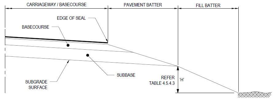
Figure 4.12.1: Pavement Batter Detail
Pavement batter widths shall be adopted for the various pavement depths as shown in Table 4.12.2.
|
Pavement Depth (mm) |
Pavement Batter Width (mm) |
|
150 |
900 |
|
175 |
1050 |
|
200 |
1200 |
|
225 |
1350 |
|
250 |
1500 |
|
275 |
1650 |
|
300 |
1800 |
|
325 |
1950 |
|
350 |
2100 |
|
375 |
2250 |
|
400 |
2400 |
|
425 |
2550 |
|
450 |
2700 |
|
475 |
2850 |
|
500 |
3000 |
Table 4.12.2: Pavement Batter Widths
4.4.4 Kerb Backfill
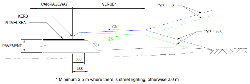
Figure 4.12.3: Typical Verge and Kerb Detail
4.4.5 Roadside Items and Traffic Management Systems
Adequate shoulder width should be provided for the location of Roadside Items and Traffic Management Systems. Electrical Assets required for consideration may include but not limited to: Closed Circuit Cameras (CCTV), Help Phones (Emergency Telephones), Intelligent Transport Systems (ITS), Lighting and Variable Message Signs (VMS).
For specific requirements refer to Main Roads Roadside Items and Traffic Management Guidelines such as:
- Close Circuit Cameras – Vehicle Detector System
- Design and Installation of Help Phones (Emergency Telephones)
- Lighting Design Guidelines for Roadway and Public Spaces
Table EA lists the possible sizes of CCTV cabinets, ITS trench, lighting poles set back distance and general slab sizes of Help Phones (Emergency Telephones). The values in Table EA are typical, specific values should be checked against in Main Roads Roadside Items and Traffic Management Guidelines.
|
CCTV Cabinet - (Refer to Main Roads Drawing 0648-3015) |
600 L x 400 W x 1200 H |
|
CCTV Double Cabinet - Refer to Main Roads Drawing 0648-3016 |
1200 L x 500 W x 1200 H |
|
Typical Trench Cross Section and Cable Pit Configuration for ITS - Refer to Main Roads Drawing 200431-0081 |
500mm W min x 500mm Depth min
|
|
Roadway Lighting Pole Set Back, for straight and curved kerbed roads - Refer to Main Roads Lighting Design Guideline for Roadway and Public Space, Section 2.1.10) |
Poles shall be set back at least 1.5m from the vertical face of the kerb or edge or carriageway. Lighting Mounting Height of 13.7m - Refer to Main Roads Standard Drawing 200231-0063 for Pole Orientation, required area behind the Light Pole, 2000mm min. |
|
Roadway Lighting Pole Set Back,where there are no kerbs - Refer to Main Roads Lighting Design Guideline for Roadway and Public Space, Section 2.1.10) |
The set back of the pole shall not be less than 3m from the edge of the traffic lane and 1.5m from the edge of shoulder. Lighting Mounting Height of 13.7m - Refer to Main Roads Standard Drawing 200231-0063 for Pole Orientation, required area behind the Light Pole, 1500mm Typical. |
|
Roadway Lighting Pole Set Back, where there is a barrier - Refer to Lighting Design Guideline for Roadway and Public Space, Section 2.1.10) |
The set back of the pole shall be at least equal to the dynamic deflection of the barrier, but no less than 1m from the barrier in a direction away from the road. Lighting Mounting Height of 13.7m - Refer to Main Roads Standard Drawing 200231-0063 for Pole Orientation, required area behind the Light Pole, 2000mm min. |
|
Roadway Lighting Pole Set Back - Refer to Main Roads Lighting Design Guideline for Roadway and Public Space, Section 2.1.10) |
On no account shall the pole be mounted on the road shoulder. Lighting Mounting Height of 13.7m. |
|
Roadway Lighting Pole Set Back, for Roundabouts and medians - Refer to Main Roads Lighting Design Guideline for Roadway and Public Space, Section 2.1.12) |
Lighting poles shall not be installed in the centre of roundabouts or around the periphery of the raised island of the roundabout. |
|
Roadway Lighting Pole Set Back, for Intersections - Refer to Main Roads Lighting Design Guidelines for Roadway and Public Spaces, Section 2.1.13 and 2.2) |
Various overhang values used by Main Roads shall be 0.0, 1.5, 2.5, 3.5 and 4.5m. Lighting Mounting Height of 13.7m. |
|
Public Spaces (Pathways and Cycle Ways) Lighting - Refer to Main Roads Lighting Design Guidelines for Roadway and Public Spaces, Section 2.3) |
Desirable pole set back should be 1.0m from edge of path. Pedestrian Mounting height of 7.0m. Outreach length for Pedestrian lighting is to be 0.0 to 1.5m. |
|
Emergency Telephones General Slab Size - Refer to Main Roads Drawing 9220-0670) |
3500 W x 2200 L. Spacing between telephones range from 200m to 1000m - Refer to Section 3.2 of Main Roads Design and Installation of Help Phones (Emergency Telephones) |
Table EA: - Possible Sizes and Set Back Distance for Electrical Assets
4.5 Batters
4.5.4 Main Roads Typical Batters
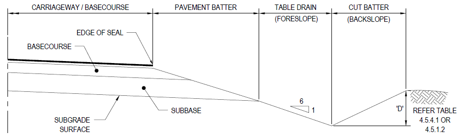
Figure 4.5.4.1 Typical Section in Cut with Table Drain
|
Depth 'D' |
Slope (H to V) |
|
0 to 2500 |
4 to 1(i) |
|
2500+ |
3 to 1(ii) |
- Transition from 4 to 1 to 3 to 1 should occur over 20m
- Batters 3 to 1 or steeper will generally require road safety barriers
Table 4.5.4.1 - Desirable Earth Cut Batters
|
Depth 'D' |
Slope (H to V) |
|
0 to 1000 |
1 to 1(i) |
|
1000+ |
0.5 to 1 |
- Transition from 1 to 1 to 0.5 to 1 should occur over 20m
Table 4.5.4.2 - Desirable Rock Cut Batters
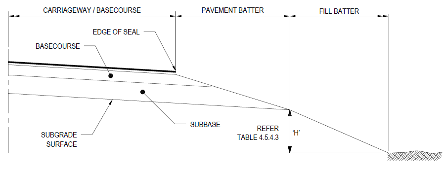
Figure 4.5.4.2 Typical Section in Fill
|
Height 'H' |
Slope (H to V) |
|
|
0 to 300 |
1.8m table drain |
|
|
300 to 1000 |
6 to 1(i) |
|
|
1000+ |
4 to 1 |
|
(i) Transition from 6 to 1 to 4 to 1 should occur over 20m
Table 4.5.4.3 – Desirable Fill Batters
Batter slopes steeper than 1:4 should be assessed for road safety barrier treatment. Steeper batters are more difficult to re-vegetate and maintain.
4.6.4 Kerb and Channel
Kerb and channel are typically not used by Main Roads.
Refer to Standard Drawing No. 9331-0376 for Main Roads kerb types.
4.8 Bicycle Lanes
4.8.1 General
It is not Main Roads practice to use kerb and channel for drainage purposes, therefore widths specified for exclusive bicycle lanes shall be taken from the face of the adjacent left hand kerb.
State roads in urban environments
Cyclists are permitted to ride on urban state roads except freeways unless otherwise signed.
New or widened roads shall be constructed with sealed shoulders that are continuous through intersections. Alternatively a shared path constructed adjacent to the road may be deemed more appropriate. (Refer to Austroads GRD Part 6A: Pedestrian and Cyclist Paths - 2017). Where neither option is possible, an alternative route with cycling facilities that meet the requirements of the relevant guidelines for on road cycling shall be identified and appropriately signed on parallel roads subject to the agreement of the Local Government Authority.
On existing roads, the facilities described above for new roads will only be provided in conjunction with any upgrades involving widening of the road, and where land is available within the existing road reserve or if land is being resumed for other purposes.
State roads in rural environments
On new or widened rural roads, the following factors shall be considered when assessing cycling facility requirements:
- The safety and security of all road users; taking into account the volume, type (with particular emphasis on heavy vehicles) and speed of motor vehicles and the potential for user conflict.
- Trip purpose and usage of the road. Consider whether the road provides a connecting link for community access; and the level of use by cyclists. Where daily cyclist volumes are greater than 25 specific cycling facilities should be installed.
Cycling facilities on rural roads shall be to the same standards as those required for urban state and main roads.
No specific provision shall be made for cyclists on unsealed roads under the responsibility of Main Roads.
4.8.9 Sealed Shoulders
Austroads GRD Part 3 implies that the use of sealed shoulders for cyclists is for un-kerbed roads. Sealed shoulders are Main Roads predominant on-road cycling facility and are applicable to both kerbed and un-kerbed roads.
4.9 High Occupancy Vehicle (HOV) Lanes
Bus lanes are typically installed as the kerbside (left most) lane, where cyclists predominantly travel. Wider kerbside bus lanes are not specifically provided unless there are found to be high numbers of cyclists and buses sharing the lane.
4.12 Bus Stops
For information relating to bus stops refer to Main Roads Supplement to Austroads GRD Part 4: Intersections and Crossings General.
5. Sight Distance
5.1 General
A reaction time of 1.5 seconds shall not be used in Western Australia.
When deriving stopping sight distances for cars on sealed roads as shown in Austroads GRD Part 3 (2016) Table 5.5 a coefficient of deceleration (d) of 0.36 shall be used in Western Australia.
For Approach Sight Distance (ASD) and Safe Intersection Sight Distance (SISD) requirements refer to Main Roads Supplement to Austroads GRD Part 4A: Unsignalised and Signalised Intersections.
5.3.2 Truck Stopping Sight Distance
Austroads Figure 5.3: Trucking Stopping Sight Distance shows a vertical clearance of 5.3m. This is a nominal figure only and should not be used as an acceptable vertical clearance for all structures.
For more specific requirements relating to vertical clearances refer to Chapter 8.2.4.
5.4.1 Benching for Visibility on Horizontal Curves
In cut situations the required line of sight should not encroach beyond the invert of the table drain as over time the growth of vegetation may reduce the effective line of sight.
5.5.2 Requirements where there is no Line of Sight over Roadside
The maximum Coefficient of Deceleration to be adopted for this section is 0.46.
6. Coordination of Horiztonal and Vertical Alignment
6.2 Safety Considerations
The design speed of the road in both the horizontal and vertical planes should generally be the same. A reduction in the vertical design speed (compared to the proposed horizontal design speed) should be treated as an Extended Design Domain design and should only be considered when;
- the terrain is such that significant cost reductions may be achieved, or
- use of the Normal Design Domain design speed will result in unacceptable environmental or heritage impacts, and
- an Extended Design Domain report has been prepared and approved by the Manager Road & Traffic Engineering. The supporting documentation should determine the risks, and propose measures to address them.
It should be noted that lack of sight distance is not a significant control on driver speed. Drivers tend to maintain their speed over crests or around horizontal curves regardless of the distance they can see ahead. Most drivers must see a hazard to be aware of it, few anticipate one.
The vertical design speed shall not be reduced in the vicinity of intersections. In the intersection zone sight distance to a zero object height shall be achieved at all times.
6.4 Drainage Considerations
In order to ensure adequate kerbside drainage the following minimum longitudinal grades shall be used:
- 0.5% Desirable
- 0.3% Absolute
For specific details relating to drainage considerations refer to the Austroads Guide to Road Design Part 5A, (2013).
7. Horizontal Alignment
7.5.1 Compound Curves
In the direction of travel the ratio of the flatter radius to the sharper radius should not exceed 1.5:1. A maximum ratio of 2:1 may be used at intersections and ramps. (Reference: A Policy on Geometric Design of Highways and Streets", AASHTO, 2004, p201.)
7.5.4 Transition Curves
Before a curve radius is finally selected it is generally necessary to give consideration to the transitions. Two types of transitions are generally required.
- A plan transition maybe required to give a gradual change in curvature from zero on the tangent to a value corresponding to the circular curve radius. The curve used by Main Roads for this purpose is the clothoid spiral.
- A superelevation transition is required to give a gradual change in cross section shape from a crowned or one-way crossfall section on the tangent to the superelevation section on the curve.
The practice now adopted by Main Roads is consistent with that described in Austroads GRD Part 3.
7.6 Side Friction and Minimum Curves Sizes
Due to the low thresholds set by Austroads Publication No. AP-R211, 2002 of when to design horizontal curves for trucks, Main Roads considers all roads should be designed to accommodate trucks. For this approach a single set of side friction factors (SFF) which accommodate both cars and trucks have been developed to be used in road design.
In general SFFs for cars are adopted unless the static rollover threshold (SRT) for trucks governs. Absolute SFFs are obtained by dividing the SRT of 0.35 by 1.15 which allows for steering fluctuations in curves. The desirable SFFs have been developed by adopting the average margin of safety used for cars (0.06) between 40 and 60 km/h. Refer to Table 7.5 for SFFs for both cars and trucks; these values are also adopted in the current Horizontal Curve Tables.
|
Design Speed (km/h) |
f |
|
|
Cars and Trucks |
||
|
Des max |
Abs max |
|
|
0.24 |
0.30 |
|
|
40 |
0.24 |
0.30 |
|
50 |
0.24 |
0.30 |
|
60 |
0.24 |
0.30 |
|
70 |
0.19 |
0.30 |
|
80 |
0.16 |
0.26 |
|
90 |
0.13 |
0.20 |
|
100 |
0.12 |
0.16 |
|
110 |
0.12 |
0.12 |
|
120 |
0.11 |
0.11 |
|
130 |
0.11 |
0.11 |
Table 7.5: Recommended side friction factors for cars and trucks
Notes:
- The SFF values in the table consider the effects of car/truck speed relationship and therefore no specific design speed for horizontal curves needs to be adopted for trucks.
7.6.1 Minimum Radius Values
Where the adopted design speed for a freeway or controlled access highway is 100km/h or greater and it is expected that it will be operating at more than 85% of the theoretical design capacity for more than three days per week during peak periods during the design life of the asset, a minimum horizontal curve radius of 750m shall be adopted for design. This criteria avoids horizontal geometry adversely impacting the operational performance of a freeway or controlled access highway as discussed in Austroads Guide to Smart Motorways 2016.
7.7.3 Maximum Values of Superelevation
Main Roads general maximum superelevation is limited to 6%. Values greater than 6% within the Main Roads Horizontal Curve Tables are for superelevation on turning roads and loop ramps. The absolute maximum superelevation for turning roads and loop ramps is 10%. Maximum values of superelevation are listed in Table 7.8.
Heavily laden or slow moving vehicles limit the maximum acceptable value of superelevation. The Designer should take into account the types of vehicles using the road and limit the acceptable maximum superelevation to ensure their safety. Superelevation should be limited to 6% where there is a likelihood of vehicles stopping on the ramp - e.g. due to Managed Motorways.
7.7.15 Superelevation on Bridges
Bridge Designers prefer that bridges are located on straight alignments and grades. If this is not possible, the next best situation is a bridge on constant curvature and crossfall to avoid the need for superelevation transitions on bridges.
7.8 Curves with Adverse Crossfall
Adverse crossfall occurs when the road pavement slopes down from the inside of a curve to the outside of the curve, which is contrary to normal practice. Although adverse crossfall on curves should be avoided, situations arise where this may be necessary.
Main Roads has adopted the following minimum radii for use with 3% adverse crossfall. In some situations it may be relevant to reduce the adverse crossfall to 2%. For these radii, calculations should use half the desirable maximum f for trucks, based on the values in Table 7.5 from Austroads GRD Part 3.
|
Design Speed (km/h) |
Minimum Radii (m) |
|
30 |
95 |
|
40 |
170 |
|
50 |
270 |
|
60 |
520 |
|
70 |
850 |
|
80 |
1250 |
|
90 |
1700 |
|
100 |
2250 |
|
110 |
3000 |
Table 7.12: Recommended Minimum Radii with 3% Adverse Crossfall
The values in Table 7.12 from 30 km/h to 60 km/h are based on using half the desirable maximum f for trucks as per the values in Table 7.5 from Austroads GRD Part 3. The radii for speeds higher than 60 km/h are based on rationalised and historic rationalised values.
7.9 Pavement Widening on Horizontal Curves
In relation to Table 7.13, Main Roads does not apply curve widening of less than 0.2m.
8. Vertical Alignment
8.1 General
Desirably, vertical points of intersection (VPIs) on straights should be spaced 6V or greater apart in flat terrain. Elsewhere, (i.e. at floodways, structure constraints or to suit the horizontal geometry) the spacing can be reduced as appropriate or to an absolute minimum of 3V, where V is the design speed in km/h. VPIs and vertical curves should be centred on horizontal curves and in tangent sections and should not be located in plan or superelevation transitions.
Dual carriageways with wide medians in excess of 10 metres provide the opportunity for the development of individual profiles for each carriageway. Each carriageway can be independently graded with narrow medians if barriers and retaining walls are used where required.
8.2.4 Vertical Clearances
The clearances in Table 8.1 are a guide only and will need to be confirmed with Main Roads Structural Engineering Branch, Heavy Vehicle Operations and Heavy Vehicle Policy. Absolute minimum clearance may vary depending on road classification and usage. For specific requirements relating to High Wide Loads refer to Geometric Design of High Wide Loads guideline.
8.2.7 Vehicle Clearances
For specific requirements relating to Vehicle Clearances refer to the Driveways Guideline
8.6.1 General
When determining 'K' values, consideration should be given to the stopping sight distance requirement for trucks. At intersections and approaches to intersections, sight distance to a zero object height is required to enable pavement markings to be visible to the driver.
For specific requirements on floodways refer to the Drainage and Waterways - Floodways guideline.
8.6.3 Crest Vertical Curves
The K value for crest curves should be determined using Table 8.7. A reaction time of 2.5s shall be used as the Main Roads desirable minimum and a reaction time of 2.0s shall be used as the Main Roads absolute minimum.
A 2.0s reaction time should only be adopted on rural roads with the explicit approval of Manager Road and Traffic Engineering Branch, who would treat this as a departure from standards.
|
Design Speed (km/h) |
Based on stopping sight distance (SSD) for a car(1) h1 = 1.1m h2 = 0.2m |
Based on approach sight distance (ASD) for a car(2) h1 = 1.1m h2 = 0.0m |
||
|
Minimum values for most urban and rural road types Based on d = 0.36 |
Minimum values for most urban and rural road types Based on d = 0.36 |
|||
|
Absolute Minimum RT = 2.0s |
Desirable Minimum RT = 2.5s |
Absolute Minimum RT = 2.0s |
Desirable Minimum RT = 2.5s |
|
|
40 |
3.5 |
4.6 |
7.2 |
9.3 |
|
50 |
6.8 |
8.6 |
13.8 |
17.5 |
|
60 |
11.8 |
14.7 |
24.0 |
29.8 |
|
70 |
19.1 |
23.3 |
38.9 |
47.5 |
|
80 |
29.3 |
35.2 |
59.5 |
71.6 |
|
90 |
42.9 |
51.0 |
87.3 |
103.8 |
|
100 |
60.8 |
71.4 |
123.6 |
145.3 |
|
110 |
83.6 |
97.3 |
170.0 |
198.0 |
Table 8.7: Minimum size crest curve (K value) for sealed roads (S<L)
Notes:
- If the roadway is on a grade, adjust the stopping sight distance values by the values described in Note 5 of Table 5.5 to calculate the minimum size crest curve.
- If the roadway is on a grade, adjust the approach sight distance values by the values described in Table 3.3 of Austroads GRD Part 4A: Unsignalised and Signalised Intersections (2017) to calculate the minimum size crest curve.
8.6.5 Sight Distance Criteria (Sag)
High standard roads (highways and freeways) are typically designed for the “Aesthetics Govern” range of K values shown in Table 8.9.1, however if these values cannot be achieved then the desirable K values for “Urban and Rural Roads (Headlight Criteria Govern)” should be used.
K Values for Sag Curve Design
Table 8.9.1 below replaces Austroads GRD Part 3 Figure 8.9. Main Roads practice is to adopt the desirable values in the table.
|
Design Speed (km/h)
|
Low Standard Roads |
Urban and Rural Roads |
Highway and Freeways |
||
|
(K value) |
(K value) |
(K value) |
|||
|
Absolute 0.1g |
Desirable 0.05g |
Absolute RT = 2.0s |
Desirable RT = 2.5s |
Desirable RT = 2.0s |
|
|
40 |
1.3 |
3 |
5 |
7 |
- |
|
50 |
2 |
4 |
8 |
11 |
- |
|
60 |
3 |
6 |
12 |
16 |
- |
|
70 |
4 |
8 |
16 |
21 |
- |
|
80 |
- |
- |
21 |
28 |
- |
|
90 |
- |
- |
26 |
35 |
43 |
|
100 |
- |
- |
32 |
42 |
61 |
|
110 |
- |
- |
38 |
51 |
84 |
Table 8.9.1 K Values for Sag Curves
Notes:
- Only to be adopted on low standard roads and at intersections.
- Based on a coefficient of deceleration of 0.46.
- Values chosen to match those calculated for crest curves based on a coefficient of deceleration of 0.36. It is Main Roads preferred practice to use Aesthetic Govern for high standard roads, however if these values cannot be achieved then the desirable values for Headlights Criteria Govern should be used.
For details of desirable sag vertical curves on the approaches to floodways refer to the MRWA Guidelines for Floodways.
8.6.6 Reverse/Compound/Broken Back Vertical Curves
Equation 26 is replaced with the following:
K [ (K1 + K2) / (K1 K2) ] ≤ (1 + b)
Where
|
K1 + K2 |
= |
K values of the two curves being tested |
|
K |
= |
minimum K value from Equation 20 based on ‘a’= 0.05g |
|
b |
= |
the actual distance between TPs of the adopted curves divided by the desirable buffer length 0.2 V m. |
8.6.9 Coordination of Vertical Curves with Superelevation Rounding Curves.
General rules for coordination of vertical curves with superelevation transition rounding curves:
- The main profile vertical curve should not overlap the rounding vertical curve.
- A main profile vertical curve may be compounded with a rounding vertical curve turning the same direction.
- Compound reverse vertical curves shall not be used.
- On a superelevation transition the whole pavement shall have a longitudinal fall in only one direction.
8.7.2 Earthworks Quantities
Project Managers in Main Roads require the computation of earthwork volumes for contract payment purposes.
Research has shown that discrepancies resulting from operator interpretation and methodology are the major cause of differences in volume calculations. Only software that has the functionality of prismoidal methodology shall be used to undertake volume calculations for payment for Main Roads projects.
Cross section volume calculations are only to be used for verification purposes or in the case of Tender Volumes for Mass Haul Analysis.
Refer to Survey and Mapping Standard 67/08/90 Earthworks Volume Calculations for details on earthworks quantities and calculations.
9. Auxiliary Lanes
9.4.1 General
Refer to the Policy and Application Guidelines. The shoulder on the opposing carriageway to the diverge taper is not required to be widened as shown in Figure 9.4.
9.5.2 Warrants
Current year design volume (AADT) used in Table 9.4 should be based on Passenger Car Equivalents (PCE’s) as defined in Table 4.5.1 of this Supplement.
9.9 Geometric Requirements
Merge and diverge taper lengths are to be calculated in accordance with the equations in Section 9.9.2 of the Austroads guide rather than Figure 9.4.
Typical plan layouts for a variety of passing lane configurations are shown on the following Guideline Drawings:
- 200331-0146 Right turn pocket within passing lane
- 200331-0148 Right turn treatment immediately prior to start of passing lane
- 200331-0149 Incorporating turning pockets and auxiliary lane
- 201431-0038 and 201431-0039 Alternative Merge Treatments
9.9.2 Tapers
Diverging taper
Where an overtaking lane is to be commenced close to an intersection, consideration may be given to commencing the lane in conjunction with the intersection treatment providing the entering vehicle can directly access the left lane as an acceleration lane as shown on the Guideline Drawing No. 200331-0149.
Merging taper
Desirable merge sight distance requirements at the end of auxiliary lanes are shown in Tables 9.3 & 9.6. The minimum merge sight distance required is equal to car stopping sight distance, measured from an eye height of 1.1m to a zero object height, with a coefficient of deceleration (d) of 0.36 and a reaction time of 2.5 seconds, as shown in Table 5.5.
Main Roads has adopted a merge rate of 0.6 m/s at all auxiliary lane tapers.
At the end of the 2 lane section (end of lane separation line) of the overtaking, acceleration or climbing lane an absolute minimum 2 x stopping sight distance should be provided, measured from an eye height of 1.1m to an object height of 1.25m from the start of the merge to beyond the end of the merge. This is referred to as “Continuation Sight Distance”. Refer to Figure 9.2.1 Merge Taper Detail.
If there is a median island adjacent to the merge, then the merge should be completed before the end of the island. This will prevent the overtaking vehicle straying onto the wrong side of the road.
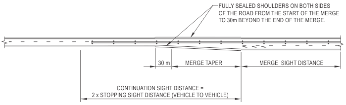
Figure 9.2.1: Merge Taper Detail
Alternative merge treatments.
For improvements to existing merges that do not meet current guidelines refer to guideline Drawings 201431-0038 and 201431-0039 for alternative merge treatments.
These options should only be used on existing merges that do not meet current road design guidelines and should not be used for new merges. These options can only be used with the approval of the Manager Road and Traffic Engineering.
9.9.3 Cross Section
Shoulder width
The shoulder to be provided adjacent to the auxiliary lane shall be as shown in Table 4.5. The shoulder should be fully sealed from the start of the merge to 30m beyond the end of the merge on both side of the road. Refer to Figure 9.2.1 above.
Crossfall
When widening for auxiliary lanes on horizontal curves, superelevation as determined from the Horizontal Curves Tables should be applied to the widening.
Lane configurations
Signing and pavement marking for auxiliary lanes that meet the current guidelines shall be as per Drawing 200631-0039.
Where there are limited overtaking opportunities between closely spaced overtaking lanes, sign G9-38 should be used “C” metres (refer to table in Drawing 200631-0039) past the end of the merge taper to indicate the distance to the next overtaking lane.
10. Bridge Considerations
10.2 Cross Section
Designers should refer to Section 11 - Bridge Widths in the Bridge Branch Design Information Document No. 3912/02, for detailed information, including the process for approval of bridge widths.
11. Appendix
Appendix A Extended Design Domain (EDD) for Geometric Road Design
A value outside the Normal Design Domain may only be used with the explicit approval of the Manager Road & Traffic Engineering, supported by a documented risk assessment that fully justifies the use of that value. The Main Roads Extended Design Domain and Design Exception process can be found here.
A.3.5 Longitudinal Deceleration
In order for a sealed road to be classified as “within a predominantly dry area", the average number of days per year with rainfall greater than 5 mm should be less than 40 with the AADT <4000 veh/d. Refer to guideline drawing No. 201831-0070 – Days of Rain.
Appendix B Emergency Aircraft Runway Strips
Main Roads has no supplementary comments for this section.
Appendix C Speed Parameter Terminology
Main Roads has no supplementary comments for this section.
Appendix D Example Calculation of the Operating Speed Model
Main Roads has no supplementary comments for this section.
Appendix E Narrow Median Treatments with Wire Rope Safety Barrier
Main Roads has no supplementary comments for this section.
Appendix F Guidance for Wide Centreline Treatments
Main Roads has no supplementary comments for this section.
Appendix G Flow Charts and Table for Determining Stopping Sight Distance Requirements for Curves with Barriers
Section G.1 comprises a detailed flowchart. In the two boxes immediately above “Change geometry” there is reference to the coefficient of deceleration of d = 0.61, this value should be substituted with 0.46. Also as per section 5.5.2 for any horizontal curve with a side friction factor greater than the desirable maximum value, the coefficient of deceleration should be reduced by 0.05.
Appendix H Theory of Movement in a Circular Path
Main Roads has no supplementary comments for this section.
Appendix I Reverse Curves
Main Roads has no supplementary comments for this section.
Appendix J Transition Curves (sprials)
Main Roads has no supplementary comments for this section.
Appendix K Vertical Curve Curvature Formulae
Main Roads has no supplementary comments for this section.
Appendix L Policy and Guidelines for Overtaking Lanes
Policy and Application Guidelines.