MRWA Supplement to Austroads Guide to Road Design - Part 5A - Drainage: Road Surface - Networks - Basins and Subsurface
Table of Contents
This Supplement has been developed to be read in conjunction with Austroads Guide to Road Design (GRD) Part 5A: Drainage – Road Surface, Networks, Basins and Subsurface (2013), a copy of which can be purchased via the Austroads website.
In Western Australia, Main Roads' policies, guidelines and standards take precedence over Austroads Guides and Standards Australia Standards. National Guides and Standards take precedence over International Guides and Standards, unless specifically stated otherwise.This Supplement has the same structure as the equivalent Austroads Guide and only additional requirements, clarifications, or practices different from Austroads appear. Where appropriate, this Supplement may also contain additional sections and figures not covered by Austroads, but the numbering sequence found in the Austroads Guide remains. Figures and tables in this Supplement replace those with the same figure or table number in the equivalent Austroads Guide.
1. Introduction
Main Roads has no supplementary comments for this section.
2. Major / Minor Drainage Concept
2.1 General
A storm event in excess of the major event is of such magnitude that there is likely to be significant disruption to the affected roads. A degree of property damage adjacent to these roads, whilst rare, should be anticipated during such an event.
2.7.2 Example 2: Major Drainage System Design
The worked example has been extracted verbatim from ARR 368 The collection and discharge of stormwater from the road infrastructure (Alderson 2006). It was originally found in ARRB Special Report No. 34 Storm drainage design in small urban catchments: a handbook for Australian practice (Argue 1986). In the process of transfer from SR34 to ARR 368 portions were omitted that may make it difficult to establish how some of the numbers in the solution have been arrived at. In such cases designers should refer to the ARRB Knowledge Base for the original SR34 Document.
3. Road Surface Drainage
Main Roads has no supplementary comments for this section.
4. Aquaplaning
4.9.3 Texture Depth
The values for texture depth contained within Table 4.1 should be used as a guide only. For example texture depth for spray seals is highly dependent on the size of aggregate used and use of the nominated 1.5mm depth may prove to be overly conservative. More accurate information may be attained through field testing or through consultation with Main Roads’ Materials Engineering Branch.
4.10.1 Assessment Criteria
- A maximum water film depth of 2.5 mm (desirable) to 3.25 mm (maximum) applies to:
- sections where the operating or design speed is 80 km/h or higher
- the approaches to and exits from intersections and roundabouts
- intersections and roundabouts
- steep downhill sections
- the merge section for entry ramps/overtaking lanes/climbing lanes
- the diverge section for exit ramps/overtaking lanes/climbing lanes
- superelevated curves (particularly those approaching limiting curve speed)
- Greater than 3.25mm and no more than 4mm – approval from Manager of Road and Traffic Engineering (treated as a Departure from Standards)
- Greater than 4mm – approval from Executive Director, Planning and Technical Services (treated as a Design Exception)
Design exemptions submitted should be supported by the design considerations and recommendations.
These should include, but not be limited to, the following where applicable:
- Evidence of reducing the film depths as much as practically possible
- Mitigations proposed to reduce any residual risk
- Crash history on existing roads, with assessment of wet weather crashes which may be attributed to aquaplaning
- The relevant drawings for context and review
4.11 Quick Assessment
Typo: the two last sentences should read if the water film depth is close to or exceeds acceptable limits, then further calculations are not needed and reworking of the road geometrics is required. If the water film depth is less than acceptable limits, then full analysis of the flow path as per Section 4.9.4 – Drainage Path and Section 4.10 – Assessment-Aquaplaning Potential, is required to confirm acceptable depths.
5. Kerbed Drainage
5.2.2 Drainage Inlet Types
The second paragraph is missing text. It should read Side entry inlets are located behind the kerb with an opening in the kerb face for capturing runoff. Due to their method of capture requiring a deviation in flow direction side entry inlets tend to be less efficient than top entry inlets.
Notwithstanding their performance disadvantages, side entry inlets may represent the preferred inlet type in particular circumstances (i.e. presence of other services) and should be used in sags where possible.
5.2.6 Non-motorised Road Users
In some instances it may not be possible to avoid encroachment of side entry inlets into abutting shared paths (including Principal Shared Paths). In such cases Main Roads’ typical setback distance of 200mm (shown on MRWA Standard Drawings for TEN, SEN, DEN and BEN structures) should be reduced to zero. It is Main Roads practice not to have any parts of the structure, frame or cover, within the path.
5.2.7 Materials
Main Roads’ preference is for the use of conventional drainage structures made from precast, steel reinforced concrete (as shown on Main Roads’ Standard Drawings). However Main Roads may approve the use of devices made from alternative materials on a case by case basis where compliance with the relevant Australian Standards has been documented.
5.2.10 Design Criteria
Any decision to deviate from the design standards detailed within AGRD 5A, or superseded by this supplement, shall require prior, written approval from Main Roads.
5.2.11 Computer Programs
For review purposes Main Roads’ preference is for designs undertaken using DRAINS (Watercom) or StormCAD (Bentley Systems) but this does not necessarily exclude the use of other programs.
Where drainage basins form part of the design then Main Roads support the use of PC_Sump (JDA Consultant Hydrologists).
5.3.1 Kerbing
Standard kerbing types may be found on Main Roads Standard Drawing 9331-0376. Designers should also refer to Main Roads Guide to the Design of Kerbing
5.3.2 Inlets
Main Roads’ Standard Drawings refer to conventional inlets such as street gullies and side entry inlets. The use of other inlets such as those detailed in AGRD 5A shall require specific approval from Main Roads and will be assessed on a case by case basis.
5.3.4 Inlet Locations
Maximum pit spacing should be in accordance with the guidance contained in AGRD 5A Section 6.3.1. Note that for such purposes inlet pits are also considered to be an accessible chamber.
5.4.2 Pavement Spread and Gutter Flow Limits
Main Roads support a number of amendments to Table 5.1. A revised version of the table is presented for use as follows:
Table 5.1: Allowable spread widths and gutter flows
|
General requirements (10 year ARI) |
||
|
Number of trafficable lanes in any one direction |
Design Speed |
|
|
<= 70 km/hr |
> 70 km/r |
|
|
1 |
1.0m |
0.75m |
|
2+ |
1.5m |
1.25m |
|
||
|
Specific requirements |
||
|
Freeways /Future Freeways |
Surface flows should be confined to the shoulders except where shoulders are less than 1.25m, in which case the allowable spread shall be 1.25m (including shoulder). |
|
|
On major roads, such as freeways, highways and arterial roads an adequate drainage system should be provided, if necessary, to limit spread width to the extent that at least one lane in each direction shall remain “dry” (i.e. free of spread) at all times during the 100 year ARI Storm. |
||
|
Others Main Roads |
No lane shall become untrafficable for more than one hour during the 100 year ARI storm. An untrafficable lane is one where more than 200mm of static head occurs anywhere within the lane. |
|
|
Secondary roads and residential streets |
At least one lane each way on secondary roads, and at least one lane width on residential streets, should be trafficable during the 5 year ARI storm or to the requirements of the local road agency.
|
|
|
Arterials |
There should be no need to change lanes during the design storm. Where traffic lanes less than 3.5m are used, it is not practical to achieve the goal of not changing lanes during the design storm when trucks and buses are considered. Where commercial vehicles comprise a significant proportion of the traffic, consider redistribution of lane widths to give a wider outer lane.
|
|
|
Auxiliary Lanes and turning pockets |
Spread widths at the commencement of auxiliary / turning lanes tapers, should be limited to 1.5m except where cycle lanes or sealed shoulders are extended through the taper. In such cases up to 1.0m of the cycle lane may be utilised for spread allowances, giving a total maximum spread of 2.5m. |
|
|
Pedestrians |
Maximum spread from the kerb immediately upstream of pedestrian crossing points should be 0.75m.
Maximum spread into the kerbside lane adjacent to bus stops or at other locations where pedestrians are expected in significant numbers, should be 0.75 m.
The design rainfall intensity to use for pedestrian facilities should be the lesser of the one year ARI, 5 minute duration, or 50 mm/hr |
|
|
Cyclists |
For dedicated cycle lanes, the spread width shall be half the cycle lane width or 0.75m, whichever is the greater.
For shared bicycle and vehicle lanes (lanes >4.1m), the gutter flow spread width should be limited to 1.5m.
The design rainfall intensity to use for these on-road cyclist checks is the lesser of the one year ARI, five minute duration, or 50 mm/hr. |
|
|
On-street parking |
Gutter flow spread width should be restricted to 2.0m for the two year ARI. |
|
|
Cross carriageway flows |
Flows across the carriageway such as those occurring at superelevation changes, median breaks, T intersections of local streets or at the end of islands shall be less than 5 L/s to reduce the risk of aquaplaning.
The design rainfall intensity to use for this situation should be the lesser of one year ARI, five minute duration or 50mm/hr. See Section 4.9.5 for further information. |
|
|
Local Road Intersections |
Flows past terminating local roads shall be limited to 30 L/s for the applicable local authority design ARI. |
|
|
General Requirements (Safety) |
||
|
Arterial roads |
Maximum flow depth x velocity = 0.3 m2/s |
|
|
Kerb-side flows / depths |
For road user safety, the maximum depth at the kerb side should be no greater than the top of kerb, and the product of gutter flow depth by average velocity (dg x Vave) should not exceed 0.4m2/s. |
|
|
Braking areas |
Water depth and width should be restricted at the approach to traffic signals, freeway ramp gores and in other areas where braking would be expected to occur frequently. |
|
5.4.4 Pit Size / Depth
Pits up to 7.2m deep (excluding cover slab) shall be per Main Roads Standard Drawings unless noted otherwise.
6. Piped Networks
6.3.1 Access Chambers
The maximum spacing for access chambers contained in this Section shall also be used for inlet pits and as such supersedes the guidance contained within Section 5.3.4.
6.3.3 Materials
The use of masonry blockwork and bricks for selected pit construction is still supported by Main Roads. Refer to the relevant Main Roads Standard Drawings for further details.
6.4.3 Bedding and Haunch Support
The default bedding and haunch support conditions on Main Roads projects shall be per Standard Drawing 200131-062. In particular this requires the use of cement stabilised backfill for all trafficable pipes installed using the trench method, multi-barrel pipes installed using the embankment method, and end treatments using the trench method.
6.5.2 Size (Access Chambers)
Main Roads recommend the use of step irons once the depth of the pit exceeds 900mm between the road surface and the floor of the pit.
Main Roads acknowledge that in some instances it may not be possible to orientate step irons such that persons can face oncoming traffic
6.5.2 Size (Pipe)
Main Roads acceptable minimum pipe size for piped networks is 300mm. Note that for culverts the minimum pipe size shall be 375mm.
Main Roads do not support the downsizing of pipe for downstream sections of pipe.
6.5.4 Pipe Velocities and Grades
Acceptable pipe grades for pipes flowing full but not under pressure shall be per the following:
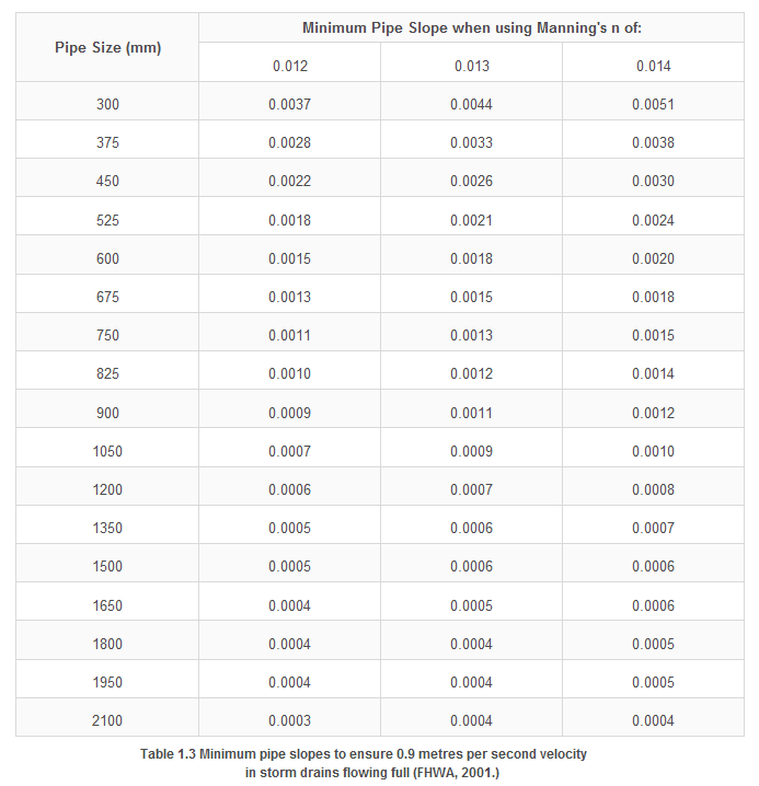
Table 6.8: Minimum pipe slopes to ensure 0.9 meters per second velocity
in stormwater drains flowing full (FHWA,2001.)
6.5.5 Clearances
Minimum clearances should in in accordance with the Utility Providers Code of Practice document.
7. Drainage Basins
7.1 Introduction
Main Roads has no supplementary comments for this section.
7.2.4 Design Principles – Detention Basins
Basins shall be checked for the major event (i.e. up to the 100 year ARI) to ensure that there is no damage to adjacent properties and / or suitable overland flow paths exist for such storms.
In trapped low locations having no identified overland flow path available, basins should be designed to accommodate up to the 100 year ARI event. In such situations the requirement for lanes to remain trafficable (as detailed in Section 5.4.2 of this supplement) shall apply.
Where possible, there should be no export of runoff from basins during the common rainfall event. Note the common rainfall event can be considered as where 16mm of rainfall falls over an hour or more.
Where large basins have been designed in accordance with A.N.C.O.L.D. guidelines the designer should review that document’s guidance for determining an appropriate ARI to check for failure of the spillway and / or embankment during the Extreme Flood. The recommended ARI is based upon consideration of the incremental hazard associated with failure. Refer to A.N.C.O.L.D. (2000) for further information.
7.2.7 Initial Design and Feasibility
The absolute maximum depth in detention basins shall be 1.5m.
7.2.9 Other Design Considerations
Main Roads practice is for detention basins to have batter slopes no steeper than 6 (horizontal) to 1 (vertical) above the invert of the basin outlet and batter slopes no steeper than 3 (horizontal) to 1 (vertical) below the invert of the basin outlet.
Main Roads practice is to provide fencing around detention basins having batter slopes steeper than 6 (horizontal) to 1 (vertical) which are accessible to the public. Where a permanent pool of water deeper than 300 mm is present then fencing is typically provided where the batter slopes are steeper than 8 (horizontal) to 1 (vertical).
Batter slopes for detention basins may constitute a roadside hazard requiring a road safety barrier system. Refer to AGRD 6, AGRD 5 and MRWA’s associated supplements for additional information.
MRWA prefer detention basins to have a length to width ratio between 3 and 30. Basins having ratios outside of this range may result in pockets of poor circulation or high velocities respectively.
Access routes for maintenance vehicles shall be provided for all basins.
7.3 Extended Detention Basins
Main Roads has no supplementary comments for this section.
7.4 Retention Basins
For local design theory relating to retention basins MRWA recommends referring to the PC_Sump Users Guide (available through JDA Consultant Hydrologists) or alternatively the paper The Disposal of Stormwater Runoff by Soakage in Perth, Western Australia written by Geoffrey Cocks and presented at the IPWEA State Conference, March 2007.
7.4.5 Design Criteria – Retention Basins
Retention (or infiltration) basins shall have depths limited to 1.5m.
The base level of retention basins should be above the Maximum Groundwater Level
Refer also to Section 7.2.9 for AGRD 5A’s guidance for detention basins relating to maintenance vehicle access.
Main Roads practice is for retention basins to have batter slopes no steeper than 3 (horizontal) to 1 (vertical).
Main Roads’ requirement for fencing around retention basins shall be as detailed in Section 7.2.9 of this supplement for fencing around detention basins.
8. Subsurface Drainage
8.3 Sources of Moisture
Some moisture is always present in the subgrade and unbound paving materials due to capillary moisture movement controlled by the environment. If this becomes excessive the subgrade and pavement can be weakened appreciably. Consequently it is important to minimise ingress of water into the pavement and subgrade.
Knowledge of the source of moisture and methods by which it can enter a road structure is of paramount importance for the adequate design of a subsoil drainage system. The main mechanisms, by which moisture can enter a road subgrade and pavement, as shown in Figure 8.12, are:
- Seepage from higher ground.
- Upward movement of a water-table under a road.
- Rainfall infiltration through the road surfacing.
- Capillary moisture from ponded water within the verges.
- Capillary moisture from the water-table.
- Vapour movements from below the road.
- Lateral seepage of moisture through pavement materials comprising the road shoulder.
|
|
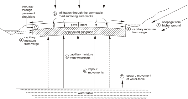
Figure 8.12: Sources of Moisture and ways by which water enters subgrade and pavement
Vapour movements (6) and lateral seepage (7) are both difficult problems to deal with and often only arise because the capacity of a drainage system to cope with mechanisms (1) to (5) is inadequate. If the road drainage system can successfully remove moisture entering via mechanisms (1) to (5) then mechanisms (6) and (7) are unlikely to occur.
Before a subsurface drainage system is designed, investigations should be carried out to provide an understanding of the range of groundwater conditions present at the site, with the results included in the geotechnical investigation report.
8.5 Types of Subsurface Drains
The following figures show examples of subsoil drains in relation to the roadway:
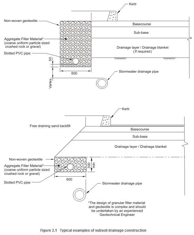
Figure 8.13 Typical examples of subsoil drainage construction
8.6.1 Longitudinal Subsoil Drains
Examples of where subsoil drains might be used are as follows:
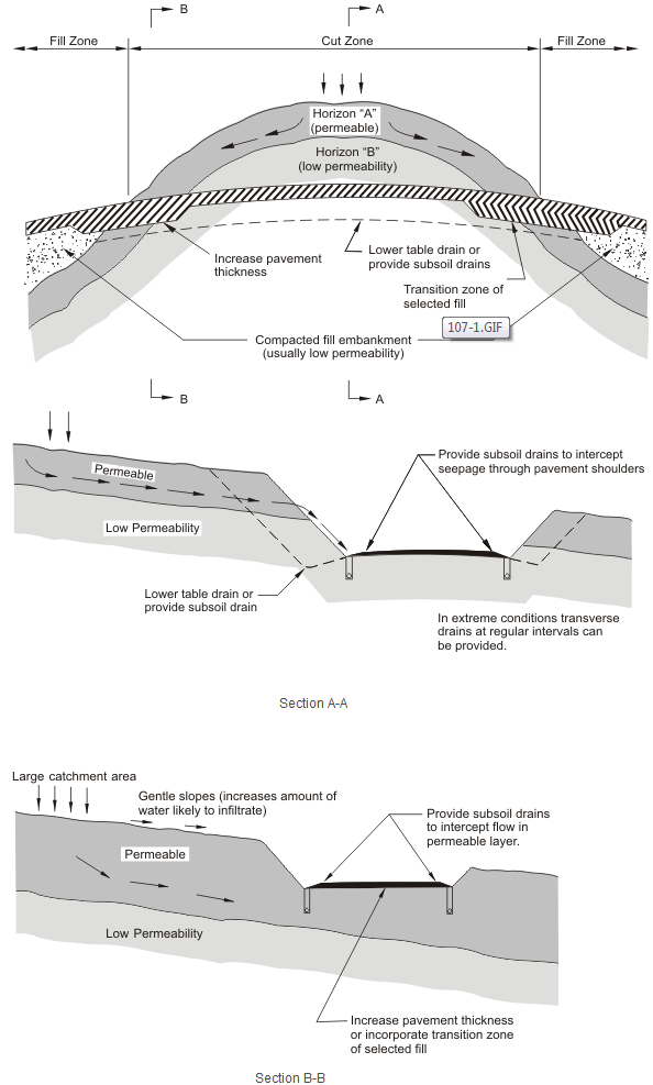
Figure 8.14: Subsoil Drains in Cuttings
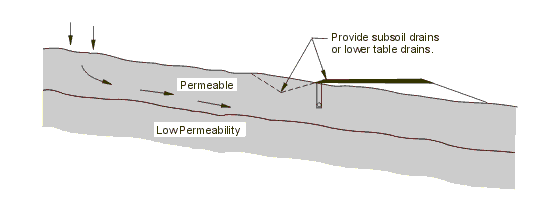
Figure 8.15: Subsoil Drains – Low Embankments
8.6.5 Locations of Subsurface Drains on Rural Roads
Where no other guidance exists, the decision to omit subsurface drainage for any new works shall be made in conjunction with the relevant Main Roads Region.
8.6.6 Access to Subsurface Drains
Intermediate flushing points or manholes along slotted subsoil drains must be provided at maximum 60m intervals.
Unslotted subsoil drain discharge pipes must include manholes to enable flushing at maximum 100m intervals.
A typical Main Roads flushout point detail is as follows:
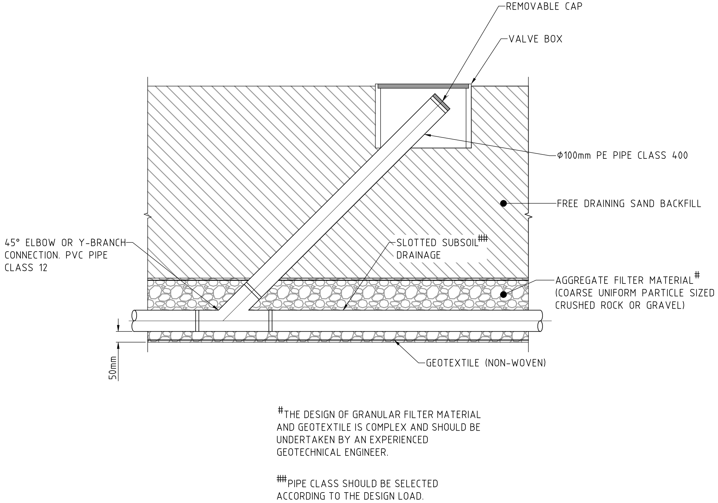
Figure 8.16: Subsoil Drains Flushout Points
8.7.4 Minimum Diameter
Main Roads preference is for subsoil drains to have a minimum diameter of 100mm.
8.9.4 Design of a Drainage Blanket to Lower a Water Table
A typical example of a drainage blanket beneath a roadway is as follows:
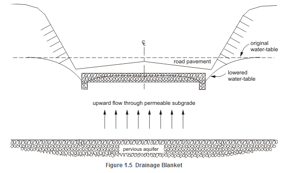
Figure 8.17: Drainage Blanket