Lighting Design Guideline for Roadway and Public Spaces
Variation Notices
There are variation notices associated with this design guideline, noted below:
- E&ITSDS-01-SVN-01 - Assessment and clarification of the updated Western Power & Horizon Power Western Australia Service and Installation Requirements Version 10
- E&ITSDS-01-SVN-02 - Clarification on the use of light emitting diode technology on Main Roads lighting network
- E&ITSDS-01-SVN-03 - Clarification of required asset drawings for lighting and switchboard assets
- E&ITSDS-01-SVN-04 - Clarification of lighting performance criteria and required drawings for lighting compliance verification
- E&ITSDS-01-SVN-06 - Cable theft mitigations in design and clarification on pit requirements
Table of Contents
- 1. General
- 2. Lighting Design
- General Requirements
- 2.2 Roadway Lighting
- 2.3 Public Spaces (Pathways and Cycleways) Lighting
- 2.4 Supplementary Lighting for Pedestrian Crossings
- 2.5 Tunnels and Bridge Lighting
- 2.6 Underpass and Short Tunnel Lighting
- 2.7 High Mast Lighting
- 2.8 Western Power Lighting Design
- 2.9 Channelised and Signalised Intersections
- 2.10 Lighting in the Vicinity of Main Roads Roadway Lighting
- 2.11 Signalised Ramp and Roundabout Lighting
- 2.12 Road Train Assembly Area (RTAA) lighting
- 2.13 Solar Powered Lighting
- 2.14 Illuminated Advertising Signs
- 3. Lighting Components
- 4. Documentation
- 5. Design Guideline Drawings
- 6. Appendix A: Specifications for HPS Lamps & Igniters
- 7. Appendix B - Selecting a luminaire type other than approved product
1. General
Main Roads will provide roadway and pathway lighting on urban freeways, highways and Control of Access Roads with high traffic volumes and Principal Shared Paths for users to travel safely at night. These will be provided in accordance with the requirements of this guideline.
1.1 Purpose
The purpose of this document is to provide design guidelines for lighting for Road and Public Spaces, where the lighting is being built and maintained by Main Roads.
This Guideline outlines technical requirements for the design of Roadway and Pedestrian Lighting and shared paths, associated Electrical Design, Material and Lighting Software, and Documentation requirements.
1.2 References
In addition to complying with the technical requirements as outlined herein, and any requirements or regulations of the Public Utilities Office, WA, and the regulations of Western Power or other supply authorities, all roadway and pathway lighting designs shall comply with the relevant standards listed below, including all amendments thereto which are current at the date of the design.
|
|
|
|
AS 3100 |
Approval and test specifications- General requirements for electrical equipment (including all current amendments) |
|
AS 4139 |
Fibres-reinforced Pipes and Fittings (including all current amendments) |
|
AS 4282 |
Control of Obtrusive effects of outdoor lighting (including all current amendments) |
|
AS 1100.101 |
Technical Drawing-General Principles (Including all current amendments) |
|
AS 1100.401 |
Technical Drawing-Engineering survey and Engineering survey design drawing (Including all current amendments) |
|
AS/NZS 1158.0 |
Lighting for Roads and public spaces – Introduction (including all current amendments) |
|
AS/NZS 1158.1.1 |
Lighting for Roads and public spaces – Vehicular traffic (Category V) lighting – Performance & installation design requirements (including all up-to-date amendments) |
|
AS/NZS 1158.1.2 |
Road Lighting – Vehicular traffic (Category V) lighting – Guide to design, installation, operation and maintenance (including all current amendments) |
|
AS/NZS 1158.2 |
Lighting for Roads and public spaces – Computer procedures for the calculation of light technical parameters for Category V Lighting and Category P Lighting (including all current amendments) |
|
AS/NZS 1158.3.1 |
Lighting for Roads and public spaces – Pedestrian area (Category P) lighting – Performance and installation design requirements (including all current amendments) |
|
AS/NZS1158.4 |
Lighting for Roads and public spaces – Pedestrian area (Category P) lighting-Performance and design requirements |
|
AS/NZS 1158.5 – |
Lighting for roads and public spaces – Tunnels and underpasses (including all current amendments) |
|
AS/NZS 1158.6 |
Lighting for roads and public spaces – Luminaires (including all current amendments) |
|
AS/NZS 1379 |
Specification & supply of concrete (including all current amendments) |
|
AS/NZS 1680.1 |
Interior Lighting-General Principles and Recommendations (including all current amendments) |
|
AS/NZS 1796 |
Certification of Welders and Welding Supervisors (including all current amendments) |
|
AS/NZS 1798 |
Lighting poles and Brackets Arms – Preferred dimensions (including all current amendments) |
|
AS/NZS 1852.845 |
International electro technical vocabulary – Lighting (including all current amendments) |
|
AS/NZS 1906 – Series |
Retro reflective Materials and Devices for Road Traffic Control Purposes (including all current amendments) |
|
AS/NZS 2053 |
Non-metallic Conduits and Fittings (including all current amendments) |
|
AS/NZS 3000 |
Australian/New Zealand Wiring Rules (including all current amendments) |
|
AS/NZS 4677 |
Steel Utility Services Poles (including all current amendments) |
|
AS/NZS 4680 |
Hot-dip galvanized (zinc) coatings on ferrous articles (including all current amendments) |
|
AS/NZS 60598 – Series |
Luminaires (including all current amendments) |
|
AS/NZS 60901 – 2003 |
Single-capped Fluorescent Lamp – Performance Specifications (including all current amendments) |
|
IEC 60662 Ed.2.0 |
High Pressure Sodium Vapour Lamps |
|
IEC 60529 Ed.2. |
Degrees of Protection Provided by Enclosures (IP code) |
|
AS/NZS 60922 |
Auxiliaries for lamps – Ballasts for discharge lamps - General and safety requirements (including all current amendments) |
|
AS/NZS 60923 |
Auxiliaries for lamps – Ballasts for discharge lamps - Performance requirements (including all current amendments) |
|
AS/NZS 61048 – 2002 |
Auxiliaries for Lamp – Capacitors for use in tubular fluorescent and other discharge circuits – Safety Req. (including all current amendments) |
|
AS/NZS 61049 |
Auxiliaries for lamps – Capacitors for use in tubular fluorescent and other discharge circuits – Performance Req. (including all current amendments) |
|
AS/NZS 9000-Series |
Quality Systems as applicable. |
|
AS/NZS CISPR 15 |
Limits and methods of measurements of radio disturbance characteristics of electrical lighting and similar equipment. (including all current amendments) |
|
|
|
|
Austroads Parts 4, 4A, 4B, 6A, 6B |
Guide to Road Design |
|
Austroads Parts 3, 6 , 8, 10,12 |
Guide to Traffic Management |
|
CASA |
Aerodromes – CASR Part 139 |
|
Civil Aviation Regulations |
No. 94 --- Dangerous Lights: 1988 |
|
AASHTO |
Roadside Design Guidelines, 4th Edition |
1.3 Lighting Policy
For policy statement, application, approval and administration guidelines refer to online guidelines as provided below:
- Road Lighting - Part A - Policy Statement
- Road Lighting - Part B - Application & Approval Guidelines
- Road Lighting - Part D - Administration Guidelines
- Solar Powered LED Lighting Policy
2. Lighting Design
General Requirements
Definitions of terms provided in AS 3665, AS/NZS 1158.0, AS/NZS 1852.845 and Austroads Glossary of Terms and Austroads guide to road design and Traffic Managements are applicable under this Guideline.
2.1.1 Survey Background
Survey shall be obtained and show the required data concerning existing or future services at the site. All such information and data shall be formatted and stored in compliance with Main Roads WA Survey and Mapping requirements.
2.1.2 Site Constraints
Any existing Utilities, Environmental Heritage and other obstacles, which are a constraint to any components of the preferred lighting design, shall be identified.
2.1.3 Services Relocations
Where the re-location of any above or below ground services and/or obstacles is necessary in the vicinity of the proposed lighting scheme, the appropriate quotations shall be obtained and considered in the development of the design to ensure that the most economical long term solution is provided after considering both construction and ongoing costs.
2.1.4 Statutory Constraints
2.1.4.1 General
Statutory limitations on glare, impact of spilled light and lamp colour appearance and any other special local conditions affecting the lighting scheme shall be identified as described in AS/NZS 1158.1.3 and AS 4282. In particular, the following authorities shall be consulted where the proposed road lighting may adversely affect the authorities’ operations:
2.1.4.2 Airport Authority
For lighting schemes located close to airports, the Australian Civil Aviation Safety Authority and the Operator of the airport shall be consulted for possible interference with the airport’s visual navigation lights, RF equipment and aircraft operations in regard to existing height restrictions.
2.1.4.3 Railway Authority
Consultation with the railway Authority in the vicinity of proposed lighting scheme is the recommended practice as part of the lighting design process, especially with regard to the siting of the lighting poles.
2.1.4.4 Port Authority
Locations in the vicinity of Port Authority require special considerations and the designer shall contact the Port Authority to arrange for design review or accessing a copy of their conditions required under the design.
Contact details for Fremantle Ports Authority is listed below:
Manager Electrical & Mechanical Services
Fremantle Ports
Tel: (08) 9430 3555 or 9430 3312
Email: mail@fremantleports.com.au
2.1.4.5 Special Requirements
Generally, locations requiring special consideration or use of non-standard equipment or arrangement shall be identified in the design report. The designer shall liaise and confirm with the Principal on the use of non-standard equipment and arrangement for unusual situations before the finalisation of the design.
2.1.5 Calculation of Applicable Light Technical Parameters
For calculations of applicable Light Technical Parameters (LTP), refer to AS/NZS 1158.1.1, AS/NZS 1158.2, AS/NZS 1158.1.2 and AS/NZS 1158.3.1.
The maintenance factor (MF) associated with the formulated maintenance regime for the Light Technical Parameters shall be 0.7 in accordance with Main Roads principal and policy requirements and calculated as per guide provided in AS/NZS1158 series.
2.1.6 Design Methods and Rules
Design Tools and methods identified under Australian Standards AS/NZS 1158.1.1 and AS/NZS1158.3.1 and Main Roads specific requirements shall be applied.
2.1.6.1 Category V Lighting – Design Methods
|
Item |
Road Element |
Design Method |
AS/NZS reference |
|
1 |
Straight Section |
Luminance-based Computer Calculation and Illuminance-based Computer Calculation where applicable |
Clause 3.2 of AS/NZS 1158.1.1 |
|
2 |
Curved Sections |
Curved Spacing Chart Luminance-based Computer Calculations |
Clause 3.3 of AS/NZS 1158.1.1
|
|
3 |
Intersections, Junctions and other Specified Locations |
Luminance-based Computer Calculations, where applicable and Illuminance-based Computer Calculation |
Clause 3.4 of AS/NZS 1158.1.1
|
|
4 |
Isolated Intersections |
Design Rules and Illuminance based computer calculation |
Clause 3.5 of AS/NZS 1158.1.1 |
Table 1
2.1.6.2 Category P Lighting-Design requirements
All Category P lighting shall be designed in accordance with AS/NZS1158.3.1 and any specific Main Roads’ requirements as stated under clause 2.3.
Design of public lighting shall comply with the requirements of AS/NZS1158.3.1 and Table 2 and Main Roads specific requirements.
|
Item |
Road Element |
Design Category |
AS/NZS reference |
|
1 |
Roads in local areas |
P3, P4, P5 |
Table 2.1 of AS/NZS 1158.3.1
|
|
2 |
Pathways including cycle ways |
P1, P2, P3, P4 |
Table 2.2 of AS/NZS 1158.3.1 |
|
3 |
Public Activities excluding car parks |
P6, P7, P8 |
Table 2.3 of AS/NZS 1158.3.1
|
|
4 |
Connecting Elements |
P9, P10 |
Table 2.4 of AS/NZS 1158.3.1 |
|
5 |
Outdoor car parks including Roof Top car parks |
P11, P12 |
Table 2.5 of AS/NZS 1158.3.1
|
|
6 |
Road Train Assembly Area (RTAA) |
P8 |
Table 2.3 of AS/NZS 1158.3.1 |
Table 2
2.1.6.3 Departure from Design Spacing
Where necessitated at isolated points in the installation due to the presence of obstruction or structures, the design spacing may be varied by not more than 10% for any two consecutive spans. Refer to AS/NZS1158.1.1 and Clause 3.3.8 of AS/NZS 1158.3.1.
2.1.7 Computerised Calculation Software
The AS/NZS 1158 series Standard for lighting for roads and public spaces permits the use of computer programs for calculating illuminance and luminance such as the SAA STAN program, PLE, AGI, etc.
The outputs of such computerised calculations shall certify conformance to AS/NZS 1158 series requirements and specific Main Roads’ requirements.
2.1.8 Electrical Design
The design of the electrical installation shall comply with WA Electrical Regulations, Supply Authority’s Requirements, AS/NZS 3000 Wiring Rules and Section 10.4 of AS/NZS 1158.1.3.
The selection of cables with respect to size, voltage drops and other requirements shall comply with AS/NZS 3008.
The design drawings shall include but not limited to:
- Details of cable sizes, circuit diagram, main switchboard and its location,
- The electrical circuits forming the controls and switches,
- Schedules of luminaries, their poles/pits, circuits and their phases, Pole numbers, etc.
- Conduit sizes, road crossings, cable pits
- Material or equipment quantities and other relevant details. [Refer to Section 4 of this Guideline for more information]
The design shall use inter-leaved three-phase circuits for providing supply to the roadway lighting system except for some minor luminaries and other low load circuits such as Public Lighting where single-phase supply may be employed. [Refer to Clause 3.3 of this Guideline].
Three phase electrical loads shall as far as practically possible, be evenly distributed across each circuit.
The electrical design shall provide optimum cable size and length for circuit to meet all requirements within this guideline where, the cable rum is not greater than 1000m and switchboard should be installed halfway across the circuit to provide ease of access and clear visible line of sight.
2.1.9 Power Supply
Power supply shall be 415 V a.c. 50 Hz, three-phase active, neutral and earth or 240 V a.c. active, neutral and earth. Allowable voltage and frequency variations shall be as permitted by Western Australian Electrical Requirements, whose custodian is the Office of Energy.
The design shall be submitted to the Electricity Supply Authority (i.e. Western Power or some other private operator as the case may be) proposing the Point of Attachment, its location and the type of connection, that is, whether the supply shall be via an aerial cable and service pole or underground power cables in conjunction with a ground mounted service pillar. The preferred method of supplying electrical power is via underground cables.
Lighting Switchboard shall be provided with a metered supply connection as per Western Power requirements.
Where switch board is in remote area, a remote monitoring meter supply should be considered under the design.
2.1.10 Roadway Lighting Pole Set Back
Lighting poles shall be installed at the set-back distance detailed below:
- For straight and curved kerbed roads, the face of the pole shall be set back at least 1.5 metres from the vertical face of the kerb or edge of carriageway (including shoulders whether or not it is sealed).
- Where there are no kerbs, the set back of the pole shall not be less than 3.0 metres from the edge of the traffic lane and 1.5 meters from the edge of shoulder (whether or not it is sealed).
- Where there is a barrier, the face of the pole shall be set back at greater than the dynamic deflection of the barrier, in a direction away from the road. The light pole set back should be equal to the total distance for barrier’s deflection zone and barrier’s working distance plus 200 mm.
- Where there are other roadside items nearby, the pole face shall be no less than 1.0 metre away from the closest piece of roadside furniture, drainage pit, noise wall, etc..
On no account shall the pole be mounted on the road shoulder (whether sealed or unsealed), which is that designated portion of the at-grade surface contiguous with edge of the traffic lane.
2.1.11 Embankments
The road geometry design shall allow for cutting or widening of the embankment to allow for installation of the roadway lighting poles to comply with the mounting height of 13.7 meters and mounting position as per clause 2.1.10 and in accordance with Main Roads Standard drawing 0530-1456 and 0530-1457.
Further, the designer is advised to consult other relevant literature on roadside engineering such as the AASHTO NHI on Roadside Design Guideline, especially on matters relating to poles installation.
2.1.12 Roundabouts and Medians
Lighting poles shall not be installed in the centre of roundabouts or around the periphery of the raised island of the roundabout. If it is unavoidable, then AS/NZS 1158.1.3 shall be strictly followed.
Lighting poles shall not be installed in medians, raised islands, except where unavoidable due to site conditions; the pole set back requirements shall comply with Clause 6 of Appendix B of AS/NZS 1158.1.3.
2.1.13 Intersections
At T-junctions and intersections, the same principle applies to the set back and location of poles (refer to clause 2.1.10). Moreover, for a junction, which has slip lanes, the layout of the poles, (taking into account the required set back and luminaire overhang) when viewed in perspective, should give as far as possible the run of the road ahead without causing confusion or indecision in motorists.
Further, as much as is necessary to satisfy the design aims and compliance with standards and regulations, the design of the overhang of the luminaries should be such that it would not impede the flow of traffic during maintenance work on the luminaries (i.e. for a two lane carriageway, at least one lane must remain open at all times).
2.1.14 Other Considerations
When design work is undertaken, the designer shall at all times take into consideration the following requirements:
- Operating characteristics and the surrounds of the road
- High degree of safety, considering all the required clearances
- Ease of installation and accessibility
- Ease of maintainability
- Minimum capital, ongoing and maintenance costs
- Efficiency
- Close proximity of lighting scheme to roadside overhead power lines
2.1.15 Verge Width Requirements and Localised Widening
Minimum 2 m clear distance is required between the edge of light pole footing and the edge of batter for light pole installation. When the distance is less than 2 m, localised widening (refer to drawing 201331-0008) is required to provide 2 m radial clearance from edge of pole footing.
2.1.16 Emergency Stopping Bays and Light Poles Location
Refer to Technical Guidelines – Emergency Stopping Bays (D10#80939).
2.2 Roadway Lighting
The following Main Roads physical parameters shall be stringently followed when designing roadway lighting:
- The luminaire shall be fitted with High output 250 watt High Pressure Sodium (HPS) lamp.
- Minimum lighting category for roadway lighting is category V3. Both luminance and illuminance design principals shall be applied to roadway lighting designs.
- Typical mounting height for roadway lighting poles shall be 13.7 m.
- Standard 12.85 m poles (measured “straight”) shall be mounted on bridge railings or concrete parapet wall or otherwise mounted a steel stump offset from or in-line with the railing to achieve a typical 13.7 m mounting height above the road surface.
- Overhang values complying with standard outreach lengths used by Main Roads shall be 0.0, 1.5, 2.5, 3.5 and 4.5 metres.
- The road surface classification shall be taken as R3 of CIE Publication No. 27 for luminance calculations.
- Road lighting pole type shall be slip-base or impact absorbent type where there is a risk of a secondary accident to occur, such as pedestrian areas or other utilities like overhead power lines or footbridge abutments etc., or is a low speed environment (less than 80km/h). The light pole types shall be decided based on Austroads Guide to Road design Parts 6, 6A and 6B and Ausroads Guide to Traffic Management parts 3, 6 , 8, 10, 12 and Traffic Management and Infrastructure - Lessons from In-depth Crash Investigations for lighting.
- The luminaire’s optical assembly shall have an adjustable tilt of not less than +5o from the horizontal, which feature shall be inherent in the luminaire’s design. However, the upcast and any specific luminaire settings required shall be specified in the design.
2.3 Public Spaces (Pathways and Cycleways) Lighting
Main Roads requires P2 Category lighting for Principal Shared Paths to be achieved with the following additional parameters:
- Typical mounting height for column mounted Pedestrian Light poles shall be 7.0 meters.
- The outreach length for pedestrian lighting is to be 0.0 to 1.5 meters.
- The luminaire’s optical assembly shall have an adjustable tilt of not less than +5o from the horizontal, which feature shall be inherent in the luminaire’s design. However, the upcast and any specific luminaire settings required shall be specified in the design.
- All pedestrian lighting design and installation shall be High Pressure Sodium (HPS) lamps.
- Point horizontal of no less than 5 lux with vertical Lux to AS1158.3 category P2;
- At locations where a PSP intersects another Path the horizontal and vertical illuminance shall not be less than 20 lux;
- At locations of conflict and high pedestrian usage such as rail stations point horizontal and vertical illuminance of no less than 20 lux shall be achieved;
- Desirable pole setback should be 1.0m from edge of path;
- Vegetation in the vicinity of lighting is to be removed/pruned so as proposed lighting levels are maintained.
- Regular maintenance requirements for vegetation should be mentioned under design report.
- Spillage lighting level (roadway lighting only, not commercial lighting etc.) and reflectivity of any walls or surfaces in the vicinity of the lighting is to be included in lighting calculations.
- Minimum lighting category for PSP under pass lighting is P10 in accordance with AS/NZS 1158.3.1:2005.
- It is required to comply with V3 Category lighting requirements where a PSP intersects a road in accordance with AS/NZS 1158.1.1:2005.
If for any reason technical or otherwise, any of the above physical parameters cannot be satisfied and the need for the employment of unusual methods or arrangements or materials or components becomes evident, then such reasons shall be properly and duly recorded in the design documentation.
The design objectives of Category P lighting are achieved by specifying luminaire optics, lamp type, lamp watt, lumen output, mounting height, spacing of poles, setback from the edge of path or edge of kerbed path, overhang length and other physical parameters to satisfy the requirements of the sub-category required for the pathway.
The levels of lighting required are as defined by the light technical parameters in the Table 2.1 for local roads and pathways of AS/NZS 1158.3.1
Where there is a barrier, the face of the pole shall be set back at least equal to barrier’s deflection distance plus minimum of 200 mm in a direction away from the road.
2.4 Supplementary Lighting for Pedestrian Crossings
The design for supplementary pedestrian lighting for mid-block crossings shall comply with the requirements of AS/NZS 1158.4. The mounting height and the distance of the floodlights from the centre of the crossing are usually determined in accordance with AS/NZS 1158.4.
2.5 Tunnels and Bridge Lighting
Generally, the guidelines of design for Bridge and Tunnel Lighting shall comply with AS/NZS1158.5 and Austroads - Guide to Road Design Series.
Provision of Emergency Lighting for Under Bridge, Underpass and Tunnel Lighting shall be provided.
2.5.1 Under-Bridge Lighting
2.5.1.1 Category V
When designing for under bridge lighting, the preferred location of the luminaires shall be under the soffit of the bridge. The locations and the methods of mounting the support in the concrete structures for the luminaires shall be decided upon with the full consent of the Structures Engineer. Unless decided otherwise, the under-bridge luminaires shall be positioned symmetrically above and along the outer-most edges of the carriageway (i.e. over the road shoulder for ease of maintenance access. The designer shall decide on the location of luminaires so that it deters vandalism).
The layout of under-bridge lighting and the circuit diagram for V-category lighting are indicated on MRWA Drawings 0448-3009 and 0448-3010. In addition the guideline drawing 200231-0057 can be used to assist the designer in design.
2.5.1.2 Category P
The mounting height is determined by the height of the soffit of the bridge above the road surface. The number of luminaires required shall depend on width and length of the bridge, the lighting category for that road and/or path over which the bridge traverses and the luminous flux contribution from existing road luminaires.
The layout of under-bridge lighting and the circuit diagram are indicated on MRWA Drawings 0448-3011 and 9230-0921.
2.5.2 Over-bridge (Overpass) Lighting
For over-bridge lighting, the requirements of luminance shall be designed to the required Sub-category of lighting (normally V3), the same as that for the connecting road traversing the bridge. Where there is also an adjacent footpath(s), the surround illuminance shall also be designed to meet the requirements of Table 2.1 of AS/NZS 1158.1.1
For short bridges, say less than 65 metres long, it is preferable not to mount the lighting poles on the bridge but at the start and end of the bridge.
For long bridges greater than 65 metres long, it may be necessary to place poles on the bridge structure.
The light pole shall be offset at 1 metre from the railing or parapet wall but if constrained, they shall be mounted in line with the bridge railings or on top of concrete parapet wall without the steel stump considering bridge structure.
Refer to Standard Drawing numbers 0530-1456, 0530-1457, 0630-1901 and 0630-1902 for poles mounted on bridge or overpass structures.
2.6 Underpass and Short Tunnel Lighting
Clause 2.5 of this guideline should be applied when undertaking the lighting design for underpass or short tunnel lighting. It is usual to take into account the contribution of flux from other sources in the vicinity though this is often negligible given the low height of the underpass or tunnel and the comparatively high level of externally mounted road lighting luminaires. However, the multiple internal reflections from the soffit and wall of the underpass or short tunnel due to the luminaires installed therein can be taken into consideration based on AS 1680.1. The designed luminance level for the road surface should not be less than that of the road, which traverses through the underpass or tunnel.
Underpass and Tunnel lighting design would depend on the actual length and width of the underpass or short tunnel. In some cases where daylight may filter through the gap between two-separated carriageways such as it is found in some underpasses, daytime lighting may not be required. However, night lighting shall in most cases be necessary.
For underpasses which have a mixture of vehicular, cyclist and pedestrian traffic, it is important to take into account the illuminance required for direct illumination of the cyclists and pedestrian paths in addition to the luminance level for the road surface.
In underpass or short tunnel constructed strictly for pedestrians or pedestrian and cyclist traffic, the illuminance criteria shall allow for the safety and security of public when designing for daytime and night-time lighting in accordance to Clause 2.3.
If the length of the tunnel or underpass is long, the lighting design should allow for parity of lighting for eyes entering from daylight into dark and exiting into daylight environment, in addition to other lighting design considerations.
The designer would need to consider each case on its own merits according to Part 1.1 and Parts 3.1, 5 and 6 of AS/NZS 1158. The relevant MRWA Drawing for reference is 0448-3011.
Where the underpass is required to be lit during day and night, designer shall allow for supply and installation of a UPS.
2.7 High Mast Lighting
In special locations such as grade-separated interchanges or other road sections having unusual geometry or other reasons such as energy costs, aesthetics and controls of Light Pollution, it may be necessary to use high mast lighting system. Where such a need arises, the necessary information, technical data and a cost benefit analysis of such a system shall be submitted as part of the design. These shall include but not limited to the following:
- The proposed height of each mast shaft.
- The maximum and minimum dimensions of the mast shaft at the bottom and top.
- The number and dimension of the outreach arms.
- Mass of each high mast shaft, inclusive of luminaires, brackets arms and lowering/raising mechanism.
- Structural calculations to prove design can withstand the geographical conditions such as wind speed.
- Details of anchoring system regarding type and dimensions of anchor bolts and their cover, anchor bolt circle template, shaft cap, pit dimension and pit cover.
- Type of material used in the fabrication of the mast as well as the methods of fabrication, including quality control measures as required under AS/NZS 1796 and AS/NZS 9000.
- The total electrical load per mast.
- The light distribution design shall be based on the IES or other approved technical authority’s method of determining the luminance or illuminance levels, including all Isolux contour diagrams for the areas involved.
- A lowering / raising mechanism to allow maintenance to be carried out with minimum interruptions and maximum safety to both the workers and the passing road users below. The mechanism shall be similar to Main Roads Western Australia’s existing high mast mechanism for economy reasons.
- All information relating to the above shall be presented in accordance with the Section 4 of this Guideline.
2.8 Western Power Lighting Design
Main Roads may be involved in the design and construction of roads where roadway lighting would be designed to AustRoads lighting standards and involvement from Western Power may be required.
Applications for the provision of a supply for lighting, or for Western Power lighting, can be submitted via the Western Power website at www.westernpower.com.au
Where a design is considered to be finalised, the application is made via https://www/westernpower.com.au/connections/developing-land/streetlights-and-unmetered-supplies/
If the request is for an indicative cost, or a discussion with a Design Specialist is required, please use the Feasibility Study application at https://www.westernpower.com.au/services/feasibility-study/
Enquiries can be made to Western Power on 13 10 87.
2.9 Channelised and Signalised Intersections
All channelized and signalised intersections are to be provided with roadway lighting to the requirements of V3 category of lighting. And illuminance based design method shall be applied. The scope of lighting is equal to the extent of civil works with the inclusion of one existing light pole from each approach.
2.10 Lighting in the Vicinity of Main Roads Roadway Lighting
Main Roads should be consulted with regards to impact of additional lighting in proximity of Main Roads’ Lighting. This is inclusive of parking lighting, local street lighting, commercialised and sign lighting owned by others.
The designer is required to provide a copy of Lighting design report in accordance with AS/NZS1158. The report and design shall provide Glare factor, proximity and orientation of light fitting with respect to Roadway lighting and road lay out.
The designer is required to ensure the additional lighting has minimum glare factor from back spill onto the roadway lighting. The location and orientation of lighting should not compromise road safety and the roadway layout perceived by approaching traffic.
2.11 Signalised Ramp and Roundabout Lighting
Ramps with metering signals are to be provided with roadway lighting to the requirement of V3 category lighting, for the length of the ramp.
Roundabouts with metering signals are to be provided with roadway lighting to the requirement of V3 category lighting, for the signalised legs of the roundabout, up to the extent of works.
Illuminance design method shall be applied.
2.12 Road Train Assembly Area (RTAA) lighting
The following Main Roads physical parameters shall be stringently followed when designing RTAA lighting:
- The luminaires for RTAA lighting shall be flood lighting.
- Minimum lighting category for RTAA lighting is category P8 in accordance with AS/NZS 1158.3.1:2005.
- Typical mounting height for RTAA lighting poles shall be 17.9 m, and a hinged lighting pole shall be used.
2.13 Solar Powered Lighting
Refer to Design Guidelines for Solar Power Lighting.
2.14 Illuminated Advertising Signs
Refer to Guidelines for Roadside Advertising Signs.
3. Lighting Components
3.1 General Requirements
All materials used in the fabrication of the lighting components shall be of the highest quality in terms of purity and alloy content, resistance to the debilitating effects of the elements of weather, electrical and mechanical properties. They shall be manufactured to the requirements of Main Roads Specification 701, current industrial standards and shall be suitably rated for the specified duties. Quality controls instituted during their manufacture shall conform to the AS/NZS 9000 Series to ensure that their durability and functional life meet current Australian and International Standards.
3.2 Main Switchboard Requirements
All lighting circuits providing electric power to the lighting poles to be supplied from a main switchboard located in the vicinity of the road lighting scheme. The main switchboard shall accept the Western Power supply of single-phase, 240 Vac or three-phase 415 V ac, 50 Hz via a Point of Attachment, which may be an aerial-type feeder or ground mounted service pillar, or fuse pit.
3.2.1 Main Switchboard Fittings
Although, the detailed lighting design dictates the switchboards equipment list, the fittings and components of the main switchboard shall be as per Main Roads Specification 701 and Design Guideline drawing for Switchboards.
All switchboards require a DIN rail mounted Main Circuit Breaker over-current device and a separate Circuit Breaker and RCD for each lighting circuit. The circuit breakers and RCDs must comply with the requirements of AS/NZS 3000:2007. The Circuit Breakers must be correctly sized for the identified load and provide Earth Fault Protection to the circuit (acting as a backup for the RCD, using the method described in AS/NZS 3000:2007). The RCD is to have a higher current rating than that of the Circuit Breaker.
Where the switchboard is also required to provide power to a traffic signal controller, a traffic signal circuit breaker shall also be included in the Main Roads compartment. Further, in some cases, it may be necessary to include a surge diverter in the switchboard in areas or regions that experience a high degree of lightning activity. The circuit breaker design must comply with the requirements of AS/NZS 3000:2007
All voltage ratings of the component shall be rated for operation at 415 V three phase (Roadway Lighting) or 240 V single-phase (Pedestrian Lighting) supplies as applicable to the type of lighting required, i.e. roadway lighting or pedestrian lighting. Current ratings of the components shall be as determined by design.
The wiring shall be designed to allow for expansion equivalent to 20% of total load per circuit and phase,
3.2.2 Switchboard Accessibility
The position and internal arrangement of the components shall be such that a safe access is provided for installation, meter reading by Western Power personnel and subsequently maintenance. Particular attention shall also be given to the location of switches, levers, handles etc. with respect to the personnel operating and maintaining the switchboard. The switchboard dimensions and internal rear clearances shall satisfy the WA Electrical Requirements. The design location for switchboard shall be such that the door(s) are facing away from the road.
The switchboard housing design shall allow for separate compartments with unique key and its duplicates for Main Roads and Western Power as detailed in Main Roads Specification 701.
The direction the switchboard, which is positioned accordingly, allows for fitting of PECell to the exterior of switchboard housing to utilise sunlight.
3.2.3 Main Switchboard Dimensions
A Standard single door Switchboard has dimensions 650 mm (W) x 1400 mm (H) x 350 mm (D), while a standard double door Switchboard has dimensions 1300 mm (W) x 1500 mm (H) x 500 mm (D). The Switchboard is normally mounted on a reinforced concrete plinth. It also has a separate compartment for housing Western Power meter and cut outs. Refer to Main Roads Specification 701 for Supply and Installation of Roadway Lighting and Main Roads Switchboard Guideline Design drawings.
Generally, a single door Switchboard to be used for PSP lighting and RTAA lighting, while a double door Switchboard to be used for Roadway lighting.
MRWA recommends the following points to be considered when designing a switchboard:
- Single door switchboard to allow for 6 circuits and allowance to be made for expansion of the maximum load up to 12 circuits provided the requirements of clause 3.2.1 are met.
- Double door switchboard to allow for 12 circuits and allowance to be made for expansion up to 18 circuits provided the requirements of clause 3.2.1 are met.
3.2.4 UPS
Requirements of specification 713 shall be addressed where the designer is required to allow for a UPS under design considerations.
3.2.5 Residual Current Device (RCD)
All new and modified switchboards shall comply with the requirements of AS/NZS 3000 requirements. Main Roads has adopted the practice of installing 10ms delayed type RCD’s (Clipsal 4RC440G30 or equivalent) with the appropriate over current protection. AS/NZS 3000 Appendix B may assist in selection.
3.2.6 Isolation Transformer
Where it has been determined that isolation transformer is required, the designer is required to follow the PTA’s “Guideline for Earthing and Bonding in the 25kV AC Electrified – Part 4 – General Light & Power Supplies - Rev 1.1”, Section 5.2.2 Part A where the transformer is in a separate cabinet from the supplying switchboard earthed to WP.
A written approval of the proposed design should be sought from PTA.
The installation shall be EFLI compliant.
3.3 Cables and Wiring
All cable and wiring shall comply with AS/NZS 3000 and Main Roads Specification 701 for the Installation and Maintenance of Roadway Lighting. All cables shall have stranded copper conductors and double insulated PVC with an insulation rating of 0.6/1kV.
All insulation colours shall be as follows:
- Active conductors - Red (R), White (W) and Blue (B)
- Neutral conductors - Black
- Earth conductors - Yellow/Green
The voltage drop shall comply with the requirements of AS/NZS 3000 wiring rules. In any case, cabling and wiring run underground shall not be less than 2.5mm2.
Circuit number (e.g. L1, L2, L3, L4 etc.) allocated to each light pole shall be clearly marked on the design drawings.
Underground power is the preferred method of mains supply from the Power Supply Authority to the switchboard and from the switchboard to the lighting poles. The design drawing shall provide full details of type of power supply and location for Point of Attachment.
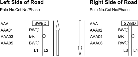
Circuits shall be so arranged that lighting poles are connected to alternate phases and circuits using separate cables. In other words, the system shall employ an interleaved circuit/alternate phase to supply power to the luminaires mounted on the poles. For a three-phase system, it is illustrated in Figure 1 below:
![]()
Figure 1
Notes:
- Symbol for Light pole and pit system.
- AAA is the Main Switchboard Number.
- L1, L2, L3 and L4 are three-phase circuits, numbered as AAAL1 or AAA L2, AAAL3 and AAAL4 inside the switchboard.
- Phases are shown as BW, WR or RB.
- Odd numbered poles are numbered as AAA01 or AAA03 or AAA05 on one side.
- Even numbered poles are numbered as AAA02 or AAA04 or AAA06 on opposite site to odd numbers side.
- Large arrows show direction of travelling motorists.
Note that the pole numbers are to be prefixed with the switchboard number. For example, assuming the switchboard numbers 'AAA', the odd number poles would be designated AAA01, AAA03 and AAA05 while the even number poles would be AAA02, AAA04 and AAA06. The numbering shall be extended to all exit and entry lanes along the lighting scheme.
Pedestrian Lighting schemes should be numbered so that numbers are in ascending order since light poles are installed on one side of the path. For example, AAA01, AAA02, AAA03, etc.![]()
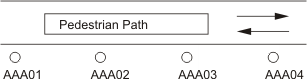
Figure 2
Note:
- For single phase circuits, circuits would be different but off the same phase.
3.4 Conduits and Road Crossings
All conduits used for running the cable shall be heavy duty PVC conduit conforming to AS/NZS 2053 Series and the amendments thereto, and shall be of the following sizes:
- 80mm conduit - between Point of Attachment (P.O.A) and Main Switchboard
- 80mm or 63mm conduit - between cable pits. 80mm conduit should be used for 25mm2 cable.
- 32mm corrugated conduit - between cable pit and pole.
The run of the conduit shall as far as possible be parallel to the carriageway and shall be located nominally 2.0 metres from the edge of the kerb or the edge of the carriageway. The conduits shall not be located under pedestrian ramps or crossings.
For road crossings, the following standard sized duct and pipe shall be used:
- 150mm PVC conduit complying with AS/NZS 2053.
- 300mm DN Fibre-Reinforced Concrete Pipe conforming to AS 4139.
- 140mm diameter Class 9 PE (preferred option).
Where these are required, the preferred method of installation is to be directional thrust-bore under and across the existing road pavement at the required depth and terminate each end of the crossing in pits which shall be located at between two to three metres from the edge of the kerb/shoulder. But where such sub-ducting is required, as for cases where telephone lines and street circuits are required to traverse the road, then the duct pits may be terminated at one metre from the duct’s ends in order to permit the installation of the various services pits at distances which will facilitate the ease of installation and maintenance of the services concerned subsequently.
When the road-crossing conduit is used as a shared service between authorities, Main Roads electrical lighting cables shall be run within an 80mm or 63mm conduit inside the road crossing.
As far as possible, all cable runs shall be continuous throughout their designed routes. Where joints are required, they shall be affected inside cable pits only.
3.5 Cable Runs, Route Markers and Identification
Any change in the conduit direction shall be shown on design drawing by showing the location of cable route markers on the concrete surround while their installation shall be in accordance with MRWA Drawing No. 200231-0063.
3.6 Luminaires
All lighting luminaires shall in general comply with the requirements of Main Roads Specification 701 - Roadway Lighting.
3.6.1 Roadway Lighting Luminaires
The listing order of the brands does not in any way indicate the order of preference. Neither do the implied specifications of proprietary brands indicate that any preferential treatment is to be accorded to these brands.
All Road lighting luminaires shall comply with AS/NZS1158.6 and AS/NZS 60598 and Main Roads Specification 701.
Main Roads' approved Roadway luminaires based on proprietary brands are:
- Thorn Alpha 2000 for general roadway lighting
- GE M-250R2
- Sylvania, B2227(R47) for general roadway lighting.
- Holophone Vector HL2A400HP24KGR for multi-lane lighting on freeways.
The 250-watt HPS lamp specified is the lamp used in a vast majority of cases but in some instances, 400-watt HPS lamp or higher may be used where the road geometry or other site conditions warrant it, as in the case of high mast lighting.
The designer shall at all times select the most suitable Luminaire for the project in terms of cost effectiveness , luminaire spacing and maintenance requirements as identified under Clause 2.1.14. The Designer’s recommendation should be finalised and submitted at 15% and 85% design review stage. Refer to Appendix B for guidance.
3.6.2 Under-Bridge Lighting Luminaires
Main Roads currently uses the following under-bridge luminaires:
- Holophane Module 600 MDWP240HP24BK for underbridge lighting applications.
- Holophane Wall Packette WL3K (WP2A070HP24GR WP1 and WP2) for walkway and architectural lighting applications.
- Thorn Meco Flood
The designer shall at all times select the most suitable Luminaire for the project in terms of cost effectiveness , luminaire spacing and maintenance requirements as identified under Clause 2.1.14. The Designer’s recommendation should be finalised and submitted at 15% and 85% design review stage. Refer to Appendix B for guidance.
3.6.3 Over-bridge/Overpass Lighting Luminaires
Luminaires for over-bridge lighting are similar to those specified for road lighting as detailed in Clause 3.6.1 above.
3.6.4 Pedestrian Lighting Luminaires
Luminaries shall comply with AS/NZS 1158.6 and AS/NZS 60598.
Main Roads currently uses the following luminaires for pedestrian and shared pathways:
- Thorn Civic 1, for general pedestrian and shared pathways
- Thorn Leopard 28 W or 38 W for pedestrian underpass lighting
The designer may propose alternatives to the above approved luminaires.
Any luminaire considered under the design must be documented and approval sought from the Principal as per Appendix B.
3.6.5 RTAA lighting luminaires
Luminaries shall comply with AS/NZS 1158.6 and AS/NZS 60598. Main Roads currently uses the following RTAA luminaires:
- GE PF-1000 PowerFlood
- Osprey MT1000B
3.6.6 Other Approved Products
Main Roads has also approved ATCO Ignitor (Catalogue No AMZN400/T1) under Lighting approved product list.
3.6.7 LED Lighting
Main Roads Western Australia is currently assessing LED lighting for roadway and pedestrian lighting. LED luminaires requirements shall conform to the standards listed below:
- IES TM 21 Projecting Long Term Lumen Maintenance of LED Light Sources
- LM-79
- IESNA LM 80-08 IES Approved Method: Measuring Lumen Maintenance of LED Light Sources
- IES LM-82-12Approved Method: Characterization of LED Light Engines and LED Lamps for Electrical and Photometric Properties as a Function of Temperature
- IESSA-Illumination Engineering Society of South Africa
- CIE 154 The maintenance of outdoor lighting systems
The designer is required to seek approval to proceed with LED lighting design at 15% design phase submission. The supporting document should be prepared in accordance with Appendix B in this document. LED lighting will be assessed using the method outlined in Appendix B.
3.7 Lighting Columns and Outreach Arms
3.7.1 Pole Type Selection
Though it is Main Roads policy to use slip-base poles for mounting the luminaires for the lighting of Freeway/Highway/Controlled Access Roads, it must be borne in mind that where use of such poles is not comparable with Main Roads standards and Australian Standards, the designer shall consider the use of impact absorbing lighting poles as recommended by the Australian Standards.
Main Roads WA currently uses various types of poles:
- Slip-base pole (in the majority) (frangible)
- Impact absorbing pole (frangible)
- Bridge mounted light poles
- Pedestrian light poles
- Joint use Roadway Light pole and Roadside Help Phones - subject to compliance with all requirements under Design Guidelines for Emergency Telephones and Main Roads Specification 702 - Emergency Roadside Telephones joint with this type of light pole should be approved by Main Roads WA prior to finalising design.
Though the vast majority of poles used are of the slip base type, the decision as to which type of pole is selected for road lighting would depend on the maximum design speed on the road, the vehicular & pedestrian traffic volumes as well as the location concerned. As a rough rule of thumb, slip-base pole shall be used in locations where the speeds are in excess of 80 kph and where a dislodge pole is not likely to cause serious injury to pedestrians or the occupants of nearby vehicles (i.e. secondary accidents).
The preferred length of the outreach is 0.0, 1.5, 2.5, 3.5, and 4.5 metres.
Use of other types of Light poles such as rigid type where applicable and in accordance with Standards shall be identified and advised by the designer prior to completion of the design.
Roadway Light Poles and outreaches shall generally conform to the requirements stated under Specification 701 and those shown on Standard Drawings.
3.7.2 Modifications to the existing lighting assets
If existing or relocated street lighting poles are within the scope of the project, the luminaires are to be fitted with new lamps and cleaned.
Any modification to the lighting requires the entire lighting asset(s) to be checked for compliance with the current standards at the time of design.
3.7.3 Standard Drawings for Light Poles
Octagonal Roadway Light poles are the preferred light poles to be installed at all new sites.
Light Poles for Roadway and Pedestrian Lighting shall conform to the following drawings:
Round Roadway Light poles (Maintenance purposes only) 9220-0636 and 9220-0637
-
- ADDITIONAL NOTES: All modification to existing sites under projects shall comply with Octagonal light poles requirements). Use of Round poles shall be limited to existing lighting schemes, if advised under the scope of work.
Octagonal Roadway light poles (Slip Base type) 0530-1456 and 0530-1457
Pedestrian Shared Path Light Pole0448-3007 and 0448-3008
- Joint use of Roadway light pole and Emergency Telephone (Impact absorbent)
Currently are not being installed. 0348-3123, 0448-3012 and 9220-670
3.8 Cable Pits
To allow the greatest flexibility on maintenance and repairs, on both 3-phase and single phase lighting systems, all roadway lighting Schemes shall utilise a cable pit system. Only Roadway Lighting Scheme requires cable pit termination next to each light pole. Main Roads uses different sizes of pits according to the function each pit is to perform. Refer to Main Roads Specification 701.
Pedestrian Lighting scheme does not normally require cable pits to be installed at each pole. However, where due to project uniqueness and site constraints the requirements of cable pits may be considered. The internal pole wiring may require to be adjusted to suit the cable pit termination within cable pit. This method should be approved at 15% design phase.
3.8.1 Main Switchboard Cable Pit
The dimensions of the main switchboard cable pi“ ("Viscount”P1" or similar) shall be of adequate size to facilitate cable installation in the 80mm and 63mm ducts inserted and fixed into the sides of the pit. Refer to Main Roads Specification 701 for supply and installation of Roadway Lighting.
3.8.2 Lighting Pole Cable Pit
Each Roadway Light Pole shall be provided with a pit to facilitate cable drawing works and the tapping-off of power to the luminaire via Tee-off point in the pit and a flexible corrugated PVC conduit to the terminals at the control gear tray located at the base of the pole. It also permits easy isolation of faulty luminaires or damaged pole in the event of a collision.
The dimensions of the pit shall be as shown on the Standard Drawing 200231-0063 which is equivalent to "Viscount”P4" or similar approved cable pit. Refer to Main Roads Specification 701 for Roadway Lighting.
The location of the pit shall be at least 0.5 metre from the pole measured in a direction away from the kerb or the edge of the shoulder of the road.
Pits shall have lid plugs and gaskets fitted to prevent water and sand ingress.
Pits associated with light poles shall have the same reference as the pole. Starting from the pit nearest to the switchboard, each pit associated with the light pole shall be prefixed with an alphanumeric reference to include the switchboard number as well, e.g. 607P1, 607P2, 607P3 etc.
3.8.3 Other Pits
Other pits shall be installed where there is a change of direction (normally 90O) of the conduit run or at the extremities of ducts across roads. They shall be similar to that specified for lighting pole pit in sub-Clause 3.8.2 above, though their dimensions may vary depending on the function intended. There shall also be a pit provided to house the earth electrode for the main switchboard.
Typical layout of conduits, ducts and their associated numbering, cable pits and pit details are indicated on Standard Drawing and 200231-0061, 200231-0063, 0530-1456 and 0530-1457.
3.8.4 Wiring size and length
The design shall allow for location of switchboard to be installed at midway of the total length of required cable run.
It is a requirement to provide an optimum cables size under the design which allows for
- Maximum cable run of 1000 meters and conforming to all requirements under AS/NZS3000,
- A two door switchboard cabinet is utilised under the design.
3.9 Referencing Convention for Switchboard, Circuit, Pole and Pit
Numbers as specified by Main Roads Western Australia shall be allocated to the switchboard and each light pole. Once the switchboard number is fixed, all other items such as circuit, pole and pit numbers shall be prefixed with the switchboard number for ease of identification. Please refer to Clause 3.8 of this Guideline for further details on referencing of circuits, poles and pits.
4. Documentation
4.1 Electrical Design Drawings
In documenting the design, drawings shall conform to MRWA's Drawing Presentation Guideline, the requirements of Section 11 of AS/NZS 1158.1.3 and Main Roads Specification 701.
Upon completion of drawings, a set of printed copies of the documents and an electronic copy of the drawings shall be submitted to Main Roads for information and retention.
4.2 As Constructed Drawings
Upon completion of all works on sites design drawings shall be amended and modified to represent the asset as built on site. The preparation of As Constructed/Asset Drawings shall be in accordance with Main Roads Design and Drawing Presentation Guideline for As Constructed Asset drawings.
5. Design Guideline Drawings
You can find Design Guideline Drawings in the Technical Library.
6. Appendix A: Specifications for HPS Lamps & Igniters
6.1 Igniter Specifications for HPS Lamps
|
Ignition voltage (250/400 watt lamp) |
~ 4 – 4.5 kVpeak |
|
Impulse Width at 2700V for 250/400 watt lamp |
~ 4 kV |
|
Ignition Voltage (1000 watt lamp) |
~ 4 – 5 kVpeak |
|
Impulse Width at 3000V for 1000 watt lamp |
³ 5 mS |
|
Restrike time after momentary interruption |
@ 4 minutes |
6.2 250 Watt HPS Lamp Specifications
|
Initial rated lumens Initial rated Lumens (High Output) |
27,500 lumens 330000 lumens |
|
Nominal lamp watts |
250 Watts |
|
Lamp Voltage |
100 V |
|
Supply Voltage |
240 V 50 Hz |
|
Nominal lamp current |
3.0 Amps |
|
Lamp Start Current-Ballast |
3.9 Amps |
|
Circuit Power Factor-Ballast |
0.38 |
|
Lamp Arc Tube Material |
Polycrystalline alumina |
|
Lamp Outer Envelope Material |
Clear borosilicate glass |
|
Efficacy |
³ 110 lmW-1 |
|
Lamp cap |
E40 |
|
Primary Voltage |
415 V 50Hz |
|
Secondary Voltage |
240 V |
|
Rating (min)-Autotransformer |
500VA continuous |
|
Shock Protection- Autotransformer |
Class 1 |
|
Regulation (max)- Autotransformer |
5% |
|
Insulation Class- Autotransformer |
H |
|
Terminals- Autotransformer and Ballast |
32Amp 16 mm2 |
|
Total Loss (hot)- Autotransformer |
10 watt |
|
Total Loss (hot)- Ballast |
26 watts |
6.3 400 Watt HPS Lamp Specifications
|
Initial rated lumens |
³ 48,000 lumens |
|
Initial rated Lumens (High Output) |
56500 lumens |
|
Nominal lamp watts |
400 watts |
|
Nominal lamp current |
~ 4.6 amps |
|
Lamp Voltage |
100 V |
|
Supply Voltage |
240 V 50 Hz |
|
Lamp Start Current-Ballast |
6.1 Amps |
|
Circuit Power Factor-Ballast |
0.40 |
|
Lamp Arc Tube Material |
Polycrystalline alumina |
|
Lamp Outer Envelope Material |
Clear borosilicate glass |
|
Efficacy |
³ 120 lmW-1 |
|
Lamp cap |
E40 |
|
Primary Voltage |
415 V 50Hz |
|
Secondary Voltage |
240 V |
|
Rating (min)-Autotransformer |
880VA continuous |
|
Shock Protection- Autotransformer |
Class 1 |
|
Regulation (max)- Autotransformer |
5% |
|
Insulation Class- Autotransformer |
H |
|
Terminals- Autotransformer and Ballast |
32Amp 16 mm2 |
|
Total Loss (hot)- Autotransformer |
18 watt |
|
Total Loss (hot)- Ballast |
37 watts |
6.4 1000 Watt HPS Lamp Specifications
|
Initial rated lumens |
³ 125,000 lumens |
|
Nominal lamp watts |
1000 watts |
|
Nominal lamp current |
~10.3 amps |
|
Lamp Arc Tube Material |
Polycrystalline alumina |
|
Lamp Outer Envelope |
Clear borosilicate glass |
|
Efficacy |
³ 132 lmW-1 |
6.5 Fluorescent lamps
These lamps shall have following Characteristics:
|
Lamp wattage |
28 |
|
Lamp cap |
GR10 |
|
Colour temperature (K) |
3500 |
|
Rated life (hours) |
10,000 |
|
Lamp lumens (lm) |
2850 |
6.6 Lamp Colour Temperature and Life
All lamps rated from 70 watts to 400 watts under Main Roads Installation shall have colour Temperature of 2000 K and life of 28500 hours.
6.7 Roadway and Pedestrian Luminaire Selection
The designer shall select luminaires and its accessories in accordance with standards listed below:
AS/NZS 1158.6 Lighting for Roads and Public space-Luminaires
AS/NZS 60598 Luminaires.
AS/NZS 60922 Auxiliaries for Lamps – Ballasts for Discharge lamps-General and safety Requirements
AS/NZS 60923 Auxiliaries for Lamps – Ballasts for Discharge lamps-Performance Requirements
AS/NZS 61347.1 LAMP control gear – General and Safety Requirements
AS/NZS 61437.2.1 Lamp Control gear-Particular requirements for Starting Devices
AS/NZS 61437.2.9 Lamp Control gear-Particular requirements for Ballasts for Discharge lamps.
7. Appendix B - Selecting a luminaire type other than approved product
7.1 Luminaire selection
Luminaire Type shall be selected in accordance with the requirements set out under Appendix A of this document and Main Roads Specification 701 - Supply and Installation of Roadway Lighting Equipment.
7.2 Propose a Luminaire type under design
It is designer’s responsibility to submit his recommendation and seek Main Roads approval.
The supporting documentation provided to Main Roads for approval could cover the information listed in the below example and any other relevant information related to the design.
7.3 Example - Information for approval
Detailed technical specifications outlining the performance of the proposed luminaire. Independently certified light technical data of the proposed luminaire (IES and CES files).
The following calculation should be treated as a working example only.
Software used to calculate the luminaire spacing – Perfect Light
Maintenance Factor – 0.7 (in accordance with main Roads maintenance scheme and AS/NZS1158 requirements)
Lamp – 250W, High Pressure Sodium.
Initial Lamp Flux(lm)=33000 lm.
Road Type – Carriageway divided, two lanes with median.
Lane Width – 3.5 meters.
Emergency Lane Width – 3.0 meters.
Verge Width – 2 meters.
Pole Setback – 1.5 meters.
Mounting Height – 13.7 meters.
Road Surface – CIE R3
Lighting Arrangement – Arrangement Number 5: Dual Carriageway - Opposite
Lighting Category - V3.
Carriageway Width = 2 x Lane width + 2 x Emergency Lane.
= 7.0 + 6.0
= 13.0 meters
Selected Luminaire - Thorn Alpha- 2000- ASN250.4/84
The maximum Spacing could be achieved is 80 meters, however, for our project it is selected to be 75 meters. This means under this project the follow applies:
For Arrangement 5 for the extent of 750 meters:
Using the Thorn Alpha luminaire, the light pole spacing is increased by 10 meters over the alternative luminaire (identify a suitable alternative, most likely the current Main Roads standard luminaire), which results in use of 20 light poles whereas a minimum of 24 light poles would be required using the alternative luminaire(s) as identified under this project, hence:
- At installation stage, a saving of 4 light poles complete with footing, outreach, internal wiring, cable pits and Luminaires would be achievable.
- Maintenance cost is reduced by approximately 16% (less number of light poles are required to be maintained).
- Running cost is reduced by approximately 16%.
- Australian Standard is still complied with.
|
Luminaire Type |
Light pole numbers |
Installation cost |
Maintenance costs |
Maintenance requirements |
Running Cost |
Compliance with Standards Yes/No |
Comments |
|
A |
X |
$$$$$$ |
$$$$$$ |
As per recommendation from manufacturer |
$$$$$ |
Yes |
Maximum Spacing of xx meters |
|
B |
X |
$$$$$$ |
$$$$$$ |
As per recommendation from manufacturer |
$$$$$ |
Yes |
Maximum Spacing of xx meters |
|
C |
X |
$$$$$$ |
$$$$$$ |
As per recommendation from manufacturer |
$$$$$ |
Yes |
Maximum Spacing of xx meters |
|
D |
X |
$$$$$$ |
$$$$$$ |
As per recommendation from manufacturer |
$$$$$ |
Yes |
Maximum Spacing of xx meters |
|
E |
X |
$$$$$$ |
$$$$$$ |
As per recommendation from manufacturer |
$$$$$ |
Yes |
Maximum Spacing of xx meters |
Conclusion:
(Recommend the best installation and justify your recommendation).