Emergency Stopping Bays and Roadside Help Phones
Table of Contents
1 Policy statement
Emergency stopping bays shall be provided on freeways and highways built to a freeway standard for safe pull off areas for broken down vehicles subject to guideline conditions, funding and work priority.
2 Application and approval
2.1 Scope
This Guideline describes Main Roads requirements for the use and location of emergency stopping bays.
2.2 Definitions
|
Term |
Definition |
|
Emergency Stopping Bay |
A location along a freeway or a highway built to a freeway standard that provides a safe pull off area for broken down vehicles and safe access to a roadside help phone. |
|
Roadside Help Phone |
A communication device for road users in the event of a break down, crash or other incident for which assistance is required. A call is automatically connected to the Main Roads Customer Information Centre when a call is initiated. |
|
Freeway |
A divided highway built to freeway standard with no access for traffic between interchanges and with grade separation at all intersections. |
|
All Lanes Running |
A traffic control measure used to increase the capacity of a freeway by replacing the emergency stopping lane with an additional traffic lane. |
|
CCTV |
Closed Circuit Television. |
2.3 Applicable Routes
Emergency stopping bays shall be installed on the following freeways and highways built to freeway standard:
- Mitchell Freeway
- Kwinana Freeway
- Graham Farmer Freeway
- Reid Highway, Erindale Road to Tonkin Highway
- Tonkin Highway, Great Northern Highway to Hale Road
- Roe Highway, Tonkin Highway to Kwinana Freeway
- Leach Highway, Tonkin Highway to Welshpool Road
When a road is upgraded to freeway standard this guideline shall be applied.
On other roads in urban areas, locations to stop beside the road and road user services are readily available. In rural areas, parking and rest areas are provided on major roads at frequent intervals and roadhouses are available to stop and make emergency phone calls in areas outside mobile phone coverage.
2.4 Approval
All proposed emergency stopping bays shall be approved by the Executive Director Road Network Operations or Executive Director Metro & Southern Regions or the Executive Director Infrastructure Delivery prior to implementation.
3 Technical guidelines
3.1 Location
Location of emergency stopping bays on applicable routes shall be subject to the following requirements:
- Sites shall be selected on the left side of the road only.
- Sites shall be between freeway interchanges
- Spacing of bays shall be no more than 3 kilometres apart except for All Lane Running where the spacing of bays is recommended to be every 500 metres but not exceed 1km.
- Sites shall be located between street lighting poles.
- Sites shall be in view of an existing or new CCTV camera.
- Safe Intersection Sight Distance at the exit point (downstream taper) shall be provided as a minimum standard.
- Sites should not be provided within 100m upstream of the start of an exit ramp or 100m downstream from the end of an entry ramp (or within 4 seconds travel time at the posted speed limit).
- Sites shall not be provided within a freeway merge area or within 100m downstream from the end of a merge area.
- Where possible, emergency stopping bays should be co-located with ITS infrastructure (e.g.: variable message signs (VMS), lane use management systems (LUMS), vehicle detection systems (VDS) cabinets, etc.) to facilitate maintenance.
3.2 Roadside Help Phones
All emergency stopping bays shall have a roadside help phone. New roadside help phones are only to be installed in emergency stopping bays.
Existing roadside help phones shall be reviewed in accordance with these guideline requirements.
Technical requirements relating to the design of roadside help phones are covered under Main Roads Specification 702.
3.2.1 Power Supply Arrangements
The source of power for roadside help phone units shall be solar.
The Solar panel is selected such that the power generated by the solar panel is of sufficient size and wattage to ensure the battery receives sufficient charge under all weather conditions. The designer is to consider the availability of adequate sun light if the solar panel is mounted near a bridge abutment, building, large trees or other potential sources of constant or intermittent shade.
3.2.2 Selection of Mounting Arrangements
The Roadside Help Phones will be mounted on a purpose-designed pillar in accordance with Main Roads WA mounting arrangements as shown in the drawing 200731-0003.
3.2.3 Identification Number (ID)
Main Roads allocates numbers (refer drawing 200731-0022) to the roadside help phones sequentially along the roadway in question, with all odd numbers and all even numbers on the same side of the freeway or highway. The Roadside Help Phones are numbered in series in the following manner:
|
Mitchell Freeway |
100 series for kerbside locations |
|
200 series for corresponding median locations |
|
|
Kwinana Freeway |
300 series |
|
Roe/Reid Highway |
400 series |
|
GFF(Graham Farmer Freeway) |
500 series |
|
Tonkin Highway |
600 series |
|
Leach Highway |
700 series |
|
Great Eastern Highway Bypass and miscellaneous (i.e. Greenmount Arrester bed) |
800 series |
Table 1: Roadside Help Phone Identification Numbers
The designer shall contact ISA Electrical Asset Co-ordinator for the next available asset number.
3.2.4 Lighting Level Requirements
The lighting level requirement for the help phone should not be less than 100 lux. This is measured on the fascia plate, with the extents being 200mm around the relevant components on the help phone fascia (push buttons and speaker).
3.3 Geometric Layout
Drawing number 200531-0019 and 201831-0001 provide layout plans for emergency stopping bays with and without safety barriers. The following requirements should be noted:
- Stopping bays shall be 60m long, inclusive of 10m tapers at either end.
- Stopping bays should be a desirable width of 6.0 metres (inclusive of sealed shoulder). A minimum width of 5.0 metres (inclusive of sealed shoulder) should only apply in the event of immovable constraints, subject to prior agreement with the relevant Main Roads Asset Manager (Metro Region) or Network Manager (other Regions).
- If the road is kerbed, then the stopping bay shall also be kerbed. The designer should ensure that the bay is self-draining with no localised ponding.
- The help phone shall be located along the wider part of the bay at the downstream side to facilitate deceleration (refer drawing number 200531-0019). Where safety barriers have been installed, the help phone shall be placed at the start of the bay and shielded by the barrier (refer drawing number 201831-0001).
- The help phone shall be able to be accessed by a person in a wheelchair (refer drawing number 200731-0003 and AS 1428.2).
- The minimum lighting level for the access area in front of the roadside help phone and at the roadside help phone shall be 10 lux.
- Foundation and base details for installing pillar mounted help phones are described in drawing number 200731-0003 for both kerbed and unkerbed installations.
3.4 Signs
3.4.1 Advance and Position Signs
Advance (MR-SAD-10) and position (MR-RPK-19) signs for emergency stopping bays shall be provided as indicated in Figure 1.
Drivers shall be informed of an upcoming emergency stopping bay at distances of 2 kilometres, 1 kilometre and 500 metres prior to the bay. Distances to emergency stopping bays already passed shall not be shown to discourage drivers from reversing back.
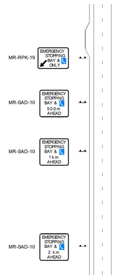
Figure 1: Signing Layout for Emergency Stopping Bays
3.4.2 Signs within Emergency Stopping Bays
Identification numbers (refer drawing number 200731-0003) shall be displayed on the roadside help phones within the emergency stopping bays to assist the Customer Information Centre and emergency services to locate the bays.
Additional signage shall be installed in stopping bays on freeways with All Lane Running to advise drivers to call 138 138 and remain in the emergency stopping bay until advised it is safe to leave. This will be further developed with the roll-out of the SMART Freeway program.
3.4.3 Customer Information Centre Signs
Drivers who are unable to stop at an emergency stopping bay can pull over to the emergency shoulder (where available) and call the Customer Information Centre on 138 138 for assistance using their mobile phone. Signs promoting the use of the 138 138 number may be installed below the Emergency Stopping Lane Only (R5-58(R)) signs as shown in Figure 2.
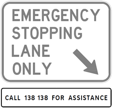
Figure 2: Call for Assistance Sign Mounted below an
Emergency Stopping Lane Only Sign
Where roadside help phones are removed, the associated redundant emergency telephone signs (MR-SAD-6) shall have decals installed on them advising to call 138 138 for help (refer drawing number 201831-0019), refer figure 3 below.

Figure 3: Call for Assistance Decal to be overlayed on
Emergency Telephone Sign
4 Design drawing presentation
4.1 Design Drawing
Design drawings shall be prepared in accordance with Main Roads Design drawing presentation guidelines.
4.2 Information to be Included
The design drawings shall include;
- Location of Emergency Stopping Bay and Roadside Help Phone.
- Type of access ramp and footing (including use of existing footing).
- Roadside Help Phone ID Number.
- Coordinates.
- Associated Road Signs.
- Sufficient notes on the design drawing to require the correct orientation of the Roadside Help Phone to be followed.
- Tie in details to kerbing, road pavement, drainage (if applicable).
- Lighting assessment including lighting level at proposed locations for all Emergency Stopping Bays and Roadside Help Phones.
- Power connection details.
- Telephone Network Selected details.
5 Drawings
The following Main Roads drawings are applicable to this guideline:
|
Drawing Number |
Title |
|
Emergency Stopping Bay – Layout Plan without a safety Barrier |
|
|
Emergency Telephones at Emergency Stopping bays – General Arrangement, Foundation and Base Details |
|
|
Emergency Stopping Bay & Help Phone Only – MR-RPK-19 |
|
|
Emergency Stopping Bay & Help Phone …. Ahead – MR-SAD-10 |
|
|
Roadside Help Phones Identification Label |
|
|
Emergency Stopping Bay – Layout Plan with a Safety Barrier |
|
|
Call For Assistance Decal – MR-SAD-14 |
|
|
Call For Assistance Drop Tag – MR-GM-47 |
6 References and related Documents
- AS1742.2 - Manual of Uniform Traffic Control Devices Part 2: Traffic Control Devices for General Use
- AS1742.6 - Manual of Uniform Traffic Control Devices Part 6: Tourist and Service Signs
- AS1743 - Road Signs-Specifications
- AS1428.2 - Design for access and mobility - Enhanced and additional requirements - Buildings and facilities.
- Austroads Guide to Road Design Part 6B: Roadside Environment
- Main Roads - Specification 702 - Supply and Installation of Emergency Telephones (Covers the Supply, Installation and commissioning requirements).