Floodways
Table of Contents
1. Purpose
These guidelines aim to ensure that all the design criteria have been considered for designing a floodway specifically from a road geometric design perspective. Guidelines for hydrological and hydraulics analysis and structural and civil engineering design of a floodway can be found in Main Roads Floodway Design Guide.
2. Introduction
Floodways are commonly used on rural roads with relatively low traffic volume and where it is impractical or uneconomical to construct a bridge or culvert.
The road geometric vertical alignment components of a floodway are outlined in Figure 1. The length of the floodway is generally taken to be the length between the intersection points of sag vertical curves, no account being taken of the extra capacity of floodway approaches or loss of capacity due to the sag vertical curves.

Figure 1: Typical Floodway (Vertical Alignement)
3. Floodway geometric design
3.1 Floodway cross section
In general, there are 5 typical floodway types and their guideline drawings are listed in Table 1. Each of the types varies in some ways from the others and their applications are explained in Main Roads Floodway Design Guide.
| Drawing No | Drawing Title |
| 9831-5499 | Floodway Approach and Floodway Type 1 Typical Cross Sections |
| 9831-5500 | Floodway Types 2 & 3 Typical Cross Sections |
| 9831-5501 | Floodway Types 4 & 5 Typical Cross Sections |
| 9831-5502 | Floodway Types 2, 3, 4, & 5 Miscellaneous Details |
Table 1: Floodway Types
A two-way crossfall is generally preferred for the following reasons:
- Vehicles traversing floodways that are overtopped by water generally travel in the middle of the road.
- A floodway and its approaches from both ends should be on a straight horizontal alignment and therefore there is no cross-fall change required.
3.2 Floodway horizontal alignment
Floodway should be on a straight horizontal alignment. When a floodway is on a horizontal curve and overtopped by water, the risks are listed below. Floodway and floodway approaches should not be located in either horizontal curves or plan/superelevation transitions.
- It is difficult for drivers to define the edge line and the edge seal and therefore a risk of vehicle steering out of the safe path.
- Any superelevation may change the normal flow distribution. The water depth will be deeper on one side of the road than the other in a superelevated section of the road. The high side is trafficable but not the low side.
3.3 Floodway vertical alignment
The visibility criteria of the floodway should meet the criteria listed below.
- Approach sight distance (ASD), eye height to zero object height (to note the hazard ahead, water, washout or scour on the pavement). ASD should be provided for drivers to notice water on the floodway, where the water is at variable levels when it starts to overtop the floodway and then rises to the maximum water level.
- Headlight criteria.
Sag vertical curves should be kept short in order not to encroach on the waterway in the floodway depression and not to increase the raised portion of the ramp more than is strictly necessary. Road embankments on the approaches to floodways are susceptible to scour and their length should be kept as short as possible. The angle of the ramp should therefore be as high as possible and consistent with other geometric requirements. A combination of 40m sag vertical curve with 0.8% longitudinal grade on floodway ramp is typically used, however, it should be noted that this combination will result in a very marginal deficiency in headlight criteria for a design speed of 110km/h with a reaction of 2.5 seconds. In this case, the length of sag vertical curve is expected to be increased slightly in order to meet the standard headlight criteria.
4. Pavement and embankment scour protection
Design guidelines for pavement and embankment scour protection for floodways can be found in Main Roads Floodway Design Guide.
The extent of cement stabilised pavement should be extended to 1% AEP water level or vertical crest VPI, whichever is lower.
The extent of embankment scour protection should be extended beyond the floodway design length to the water level extent as shown in Figure 2. Consideration should be given to minimising the closure time by ensuring the road is not damaged after the design rainfall event. Road damage repair work is always difficult in a remote area and the fund for road repair work may not always be available for road damage caused by frequent events. The recommended desirable Annual Exceedance Probability (AEP) water level for the extent of embankment scour protection is 2%.
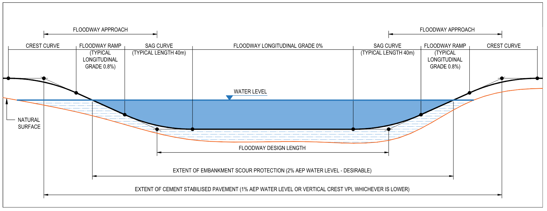
Figure 2: Pavement and Embankment Scour Protection for Floodways
5. Floodway capacity
Floodway is designed such that it can be trafficable for all flows up to the design AEP and for all flows up to 2% AEP can be contained within the floodway approach without spilling out elsewhere along the road.
6. Relief culvert for floodway
A relief culvert should be placed at the lowest point of the natural surface to drain the perennial or frequent flows. This prevents water from ponding upstream of the floodway, softening the embankment and subgrade which ultimately causes pavement failure.