MRWA Supplement to Austroads Guide to Road Design - Part 6A - Paths for Walking and Cycling
The information below is intended to reflect the preferred practice of Main Roads Western Australia (“Main Roads”). Main Roads reserves the right to update this information at any time without notice. If you have any questions or comments please contact Barry Stafford e-mail or (08) 9323 5849.
To the extent permitted by law, Main Roads, its employees, agents, authors and contributors are not liable for any loss resulting from any action taken or reliance made by you on the information herein displayed.
Table of Contents
This Supplement has been developed to be read in conjunction with the Austroads Guide to Road Design (GRD) Part 6A: Paths for Walking and Cycling (2017), a copy of which can be obtained via the Austroads website.
In Western Australia, Main Roads' policies, guidelines and standards take precedence over Austroads Guides and Standards Australia Standards. National Guides and Standards take precedence over International Guides and Standards, unless specifically stated otherwise.This Supplement has the same structure as the equivalent Austroads Guide and only additional requirements, clarifications, or practices different from Austroads appear. Where appropriate, this Supplement may also contain additional sections and figures not covered by Austroads, but the numbering sequence found in the Austroads Guide remains. Figures and tables in this Supplement replace those with the same figure or table number in the equivalent Austroads Guide.
General Standards and Application
The Department of Transport has a hierarchy for the cycle network, arranged by route function. These functional routes have various built forms as shown below:
|
Route Hierarchy |
Built Form |
|
Principal Shared Path (PSP) |
|
High quality shared paths Bi-directional protected bike lanes Protected on-road bike lanes Safe Active Street (Bicycle Boulevards) |
|
Shared Paths Bi-directional protected bike lanes Protected on-road bike lanes Safe Active Street (Bicycle Boulevards) |
The purpose of this supplement is to provide guidance for the design of Principal Shared Paths (PSPs) and High Quality Shared Paths. The term shared path in this document refers to both these path forms. When the term PSP is used, guidance only relates to PSPs.
For other paths it should be noted that since April 2016 the Road Traffic Code allows for bicycle riders of any age to use any footpath unless signage specifically prohibits bicycle riding.
All path design projects should have the following primary design objectives:
- Maximise safety.
- Minimise costs associated with construction, maintenance and use of the path.
- Minimise adverse impacts and enhance the environment where possible.
- Take into account the views of the public including local residents, businesses, community groups and path users.
- Integrate visually with the surrounding environment.
- Consider the planned ultimate layout (road and adjacent developments) in the vicinity of the works and ensure that it can be accommodated with a minimum of reconstruction in the future.
- Maximise opportunities to cater for the needs of all path user groups.
1. Introduction
1.2 Scope of this part
For signage and pavement marking refer to:
- AS 1742.9 Bicycle facilities
- Main Roads Policy and Application Guidelines, Signage and Pavement Marking on Paths
- Main Roads supplement to AS 1742.9 (Under Development)
- Main Roads guidelines for Bicycle Directional Signs
1.4 General
1.4.1 Policies and Guidelines
For links to policies and guidelines refer to Pedestrian & Cyclists area.
2. Types of Path
Main Roads has no supplementary comments for this section.
3. Path User Considerations
3.1 General
Safe
Based on Crime Prevention through Environmental Design principles shared paths must be located so that path users are always visible from a road or public open space. Exceptions to this requirement are permissible for distances of up to 100 m where unavoidable, such as at overlapping noise or screen walls.
4. Design Considerations
Main Roads has no supplementary comments for this section.
5. Design Criteria
5.1 Width of Paths
5.1.4 Shared Paths
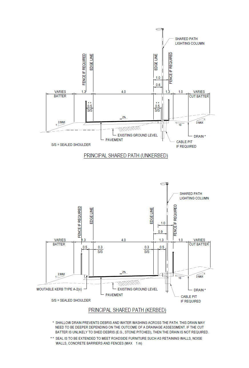
Main Roads preferred practice is to adopt the typical cross section Figure 5.1.4 for new PSPs. This typical cross section will generally avoid the need for fencing to protect users from the fill batter slopes. If fencing is required, it should be located behind the light poles so lighting can be maintained from the path, or 0.5 m clear from the trafficable path where there are no light poles.
For separated path typical cross sections refer to Department of Transport, Planning and Designing for Bike Riding in Western Australia.
Click image to enlarge
Figure 5.1.4: PSP typical cross section
Notes:
- For High Quality Shared Paths the same typical cross section should be applied, however the path and shoulder widths may vary.
5.2 Bicycle Operating Speeds
Cyclists’ operating speeds are highly affected by a range of factors as described in this section. One of these factors is gradient, for which the affects can be predicted. The Design Speeds in Table 5.5.1 should be adopted in design.
|
Design Speed (km/h) |
Grade (%) |
|
20(2) |
0 |
|
30 |
0 |
|
33 |
-1 |
|
37 |
-2 |
|
40 |
-3 |
|
43 |
-4 |
|
47 |
-5 |
|
50 |
-6 |
Table 5.5.1 Shared Path Design Speeds
Notes:
- The values in the above table are based on a design speed of 30 km/h for a level grade, increasing linearly to 50 km/h on a downgrade of 6%.
- A design speed of 20 km/h should only be used in constrained locations e.g., approaches to footbridges and underpasses.
- For all grade adjusted Design Speeds the slope length should be at least 100 m long. This is based on acceleration due to slope equation (a=g x sinθ). For shorter grade lengths the design speeds can be reduced linearly (e.g., -3 % grade 70 m long = (40 km/h – 30 km/h) x 70 m/100 m + 30 km/h = 37 km/h).
- For slopes where landing have been installed in accordance with AS1428.1 the Design Speed should be fixed at 30 km/h irrespective of the gradient.
5.3 Horizontal Curvature
Adverse superelevation occurs when the path pavement slopes down from the inside of a curve to the outside of the curve.
Main Roads has adopted the following minimum radii for use with 2% adverse crossfall.
|
Design Speed (km/h) |
Minimum Radii (m) |
|
20 |
11 |
|
30 |
27 |
|
33 |
35 |
|
37 |
44 |
|
40 |
55 |
|
43 |
68 |
|
47 |
84 |
|
50 |
103 |
Table 5.6.1 Minimum Radii with 2% Adverse Crossfall
5.3.1 Minimum Horizontal Curve Lengths
For shared paths it is desirable to set minimum horizontal curve lengths. This will assist cyclists to remain on the correct side of the path as they corner, and improve the path appearance. The equation adopted for this is:
![]()
Where V = Design Speed in km/h
Lh = minimum length of circular curve in m
5.4 Path Gradients
To avoid the need for landings on shared paths it is necessary to restrict the maximum longitudinal gradient to 3%. Where landings are unavoidable, they should be provided in accordance with AS 1428.1. Main Roads preference is to limit the longitudinal fall on landings to 2%. They must have vertical curves at least 2.0 m long at each change of grade and landings must be a minimum length of 1.6 m between the vertical curves. Landings to the side of the path are not acceptable. It is not permitted to create a landing by introducing three vertical curves to a grade line as shown in Figure 5.5.1. Landings must be created using only two vertical curves.
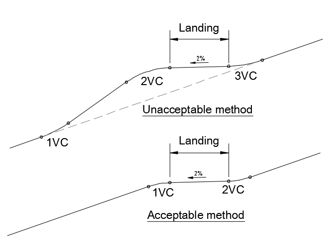
Figure 5.5.1 Methods of creating landings
A possible alternative treatment to avoid landings on the shared path would be to provide a 1.5 m wide concrete pedestrian only path to the left hand side on the uphill direction of the shared path, with 1.2 m long landings (with no vertical curves) including handrails (if required) to AS 1428.1. Signage and/or pavement markings shall be used to clearly show that wheelchair access is via the pedestrian path.
5.4.2 Ease of Uphill Travel
Main Roads does not require shared paths to comply with Figure 5.6.
5.5 Clearances, Batters and Need for Fences
5.5.2 Bicycle paths
Where shared paths have painted edge lines the clearance shall be provided from the centreline of the painted line, otherwise from the edge of the running surface.
For shared paths the following clearances shall be provided:
- 1.0 m minimum clearance from the edge of the shared or cycle path to the posts of W-beam, Thrie Beam or Modified Thrie Beam barriers or other sharp edged features. In addition it may be appropriate to install barrier post caps to reduce the risk of serious injury.
- 0.5 m minimum clearance from the edge of the path to obstacles such as fences, signs, light poles, traffic and rigid road safety barriers, balustrades, trees, walls etc.
- 1.0 m minimum clearance from the edge of the shared path to the edge of earthworks batters.
- 1.0 m minimum clearance from the edge of the path to the face of any road kerb, except on crossing approaches.
- At bridges and underpasses the approach end of any obstacle such as a fence, traffic or road safety barrier, or balustrade must be offset at least 0.5 m from the edge of the path.
Bicycle path vertical clearance
For bridges and underpasses the minimum path vertical clearance is 2.7 m. For sign structures the minimum path vertical clearance is 2.5 m.
5.5.3 Batters and Fences
Steep batter or vertical drop
To allow for the asphalt surfacing drop off at the edge of a shared path Figure 5.10 has been amended as below. In addition slopes with obstacles are not treated differently from slopes without obstacles, however shared paths will need to comply with the requirements of Section 5.5.2.
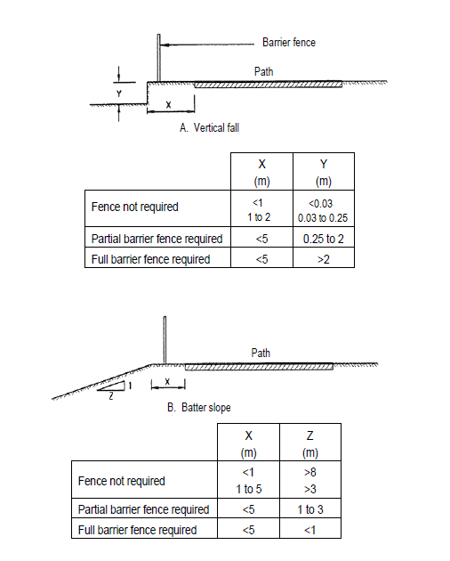
Figure 5.10 Requirement for fence barriers at batter and vertical drops
Notes:
- In addition to the requirements of Figure 5.10, if a vertical drop or slope steeper than 1:3 with a height greater than 1.5 m is located within a shared path batter slope of 1:3 or steeper, then as a minimum a fence should be installed. This requirement is to safeguard against cyclists who could leave the shared path and traverse the 1:3 slope without being able to stop prior to the drop or steep slope.
Other vertical drops
Where a structure presents a fall hazard of 1.5 m or more, and if it is likely that a person or maintenance worker could gain access to the upper level, then a pedestrian restraint system such as a Monowills 2-rail barrier must be installed to protect against the fall hazard. A fence is not acceptable on bridge abutments and elsewhere and a fence / pedestrian restraint system is not acceptable unless it has at least two horizontal rails.
5.6 Crossfall and Drainage
5.6.1 Crossfall
On shared paths Main Roads preference is to provide 2% one-way crossfall, unless superelevation is required.
5.6.2 Drainage
A minimum 5 year ARI or 20% Annual Exceedance Probability (AEP) must apply to shared paths and 10 year ARI or 10% AEP must apply to PSP serviceability and flood protection components of the design.
On shared paths the gutter flow spread should be limited to half the width of the trafficable lane. The rainfall intensity for calculating gutter flow spread limits can be limited to a maximum of 50 mm/hr.
Grates can be used to control gutter flow spread however they shall not be located in the shared path trafficable lanes. They should also be kept out of shoulders wherever possible.
Grates shall comply with the following:
- AS 1428.1 Clause 7.5 for grates on accessible paths of travel
- AS 1428.2 Clause 9(c) for gratings on walking surfaces
- AS 3996 Clause 3.1 for load classification to a minimum of Class B
- AS 3996 Clause 3.3.5 for surface openings in pedestrian areas
- AS 3996 Clause 3.3.6 for bicycle tyre penetration resistance
- AS 4586 Table 2 for wet pendulum test classification of P3
- AS 4586 Table 5 for oil-wet inclining test classification of R10 both perpendicular and parallel to the grate.
On steep sections of shared paths appropriate treatments should be provided to prevent erosion and scour of the unsealed shoulder, resulting from the design flow. Appropriate treatments may include sealing and kerbing the unsealed shoulder, broom finished concrete spoon drains or mortared rock pitching spoon drains.
Flows across the shared path such as those occurring at superelevation changes and at T-intersections of connecting paths shall be minimised and less than 5 L/s. The design rainfall intensity for calculating cross path flows can be limited to a maximum of 50mm/hr.
On approaches to underpasses consideration should be given to debris being washed onto the path from the approach batters. Therefore it may be appropriate to kerb the path and provide a 1.0 m backward sloping verges to the underpass approaches where this is likely to occur.
Desirably kerbing should be Mountable - Type A2. Barrier kerbs should not be used except where there are handrails that will prevent pedal strikes. The clearances to kerbs should be a minimum of 0.3 m from the edge line to prevent pedal strikes.
An appropriate drainage system should be provided at shared path underpasses.
ACO TraffikDrain or similar grated trench drain with boltless locking system can be considered at the ends of shared path underpasses. If a conventional drainage outlet is not available at shared path low points, soakwells or underground storage tanks can be considered. Soakwells and underground infiltration systems or storage tanks shall be designed in accordance with the Stormwater Management Manual for Western Australia, Department of Water and Environmental Regulation, 2007.
Pits for drainage, lighting or ITS shall not be located in the shared path trafficable lanes. These should also be kept out of shoulders wherever possible.
5.7 Sight Distance
5.7.1 Bicycle Path Stopping Sight Distance
For shared path design a reaction time of 2.5 seconds and a coefficient of friction of 0.16 (coefficient of deceleration [d] ) should be used.
Table 5.7.1 gives stopping sight distances on level grades for varying design speeds based on a reaction time of 2.5 seconds.
Crest and Sag Curves
|
Design Speed (km/h) |
Stopping Sight Distance (SSD) (m) |
K values Based on SSD for a bicycle h1 = 1.4 m h2 = 0.0 m d = 0.16, RT = 2.5 s |
|
20 |
24 |
2 |
|
30 |
43 |
6.6 |
|
33 |
50 |
8.8 |
|
37 |
59 |
12.6 |
|
40 |
67 |
16.1 |
|
43 |
75 |
20.3 |
|
47 |
87 |
27 |
|
50 |
96 |
33.1 |
Table 5.7.1: Minimum crest curve K values for sealed paths (S<L)
Notes:
- If the path is on a grade, it may be possible to adjust the stopping sight distance values on the same principles used in Austroads GRD Part 3.
Sag curve K values should be the same as crest curve K values to ensure comfort and achieve an aesthetically pleasing path alignment. If this cannot be achieved it may be appropriate to use comfort criteria based on 0.05g.
Safe Intersection Sight Distance
At shared path to shared path intersections SSD from Table 5.7.1 should be used for safe intersection sight distance (SISD) based on h1 = 1.4 m and h2 = 1.0 m (to allow for a child riding a smaller bike) and taken from 2 m back on the minor leg from the seal edge of the major path. Similarly to Austroads GRD Part 4A sight distance should be checked in both directions. Refer to Figure 5.15.1 for illustration of SISD checks.
If it is known that the intersection is likely to be used by young children (primary school aged), for example close to a school or park with playground equipment, then the distance back from the hold line should desirably be increased to 5.5 m. This distance allows a cyclists travelling on the major leg to observe a child travelling at an average speed of 5 km/h on the minor leg for 4 seconds (2.0 s reaction time plus 2.0 s manoeuvre time). This will give the cyclist time to better anticipate if the child is going to give way at the hold line, and take evasive action if required. Providing a specific design solution for all young cyclists is problematic due to their unpredictable nature, therefore the above criteria is an attempt to improve overall safety.
SISD checks are particularly important where noise / screen walls run parallel to the major leg at an intersection. It may be necessary to provide splays in the wall in order to achieve SISD. Any planting that may be introduced within the sight line splays should have a mature height of less than 0.6m.
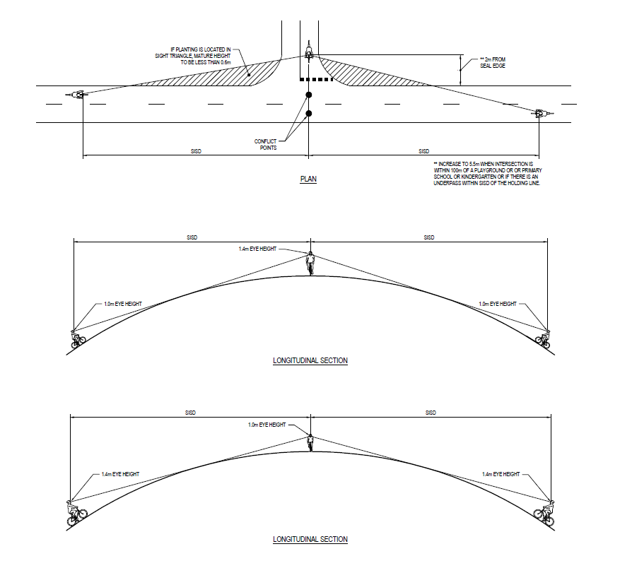
Figure 5.15.1 Safe intersection sight distance
Approach Sight Distance
SSD should be used for approach sight distance on the minor leg of an intersection, based on h1 = 1.4 m and h2 = 0 m.
5.8 Changes in Level
5.8.1 Grab rails and Ramps
The short tubular railing that Main Roads uses to indicate the presence of a kerb crossover is locally referred to as a grab rail. This differs from AS 1428.1, where the grab rail is defined as a rail used to give a stabilising assistance to a person - for example, to provide leverage to a person getting off a seat.
Drawing 9831-5649 provides the requirements for grab rails on medians and median islands that exceed 1.2 m in width. It is not appropriate to include grabrails on splitter or other islands at intersections, nor on painted island treatments.
Note that grab rails are to be located on the traffic approach side of the kerb crossover and not in the middle of the ramp where it will impede wheelchair accessibility.
Kerb crossovers shall be flush with the road surface (asphalt or seal) as shown on Drawing 9831-5649. Care should be taken to ensure that there is provision of a 1.5 m (min) level section of pathway behind the ramp. Where possible, the kerb ramp shall be aligned to reflect the direction of travel required by the user when commencing to cross the street.
5.8.2 Tactile Ground Surface Indicators (TGSIs)
Tactile ground surface indicators are designed to give warning of hazards and directional information to pedestrians who are blind or have impaired vision. Refer to AS 1428.4.1.
Rather than apply such facilities everywhere, it is appropriate to implement tactile devices at selected intersections on the basis of need. TGSIs will normally be installed on kerb ramps at intersection or mid-block crossings in Metropolitan areas. In rural centres tactile paving is less commonly applied and the need to include in a specific project should be confirmed in consultation with the local council.
Main Roads Standard Drawing 200931-0089 details set out dimensions to be used for warning tactile ground surface indicators on pedestrian ramps. Standard Drawings 200931-0090 and 200931-0091 show the particular layout requirements where used within corner and median cut throughs. Designers should also refer to AS 1428.4.1 Appendix C for details of numerous configurations of warning surface indicators used in conjunction with directional surface indicators.
5.11 Lighting
PSPs and path connections to PSPs must be fully lit. If possible light pole positions should coincide with bollard and grab rail installations. Underpasses and their approaches must be lit.
Light poles on footbridges, if required, must be attached to the side of the bridge deck. These light poles must be circular in cross-section and the same colour as the balustrade.
Lighting must be in accordance with Main Roads Lighting Design Guideline for Roadway and Public Space. Lighting for shared paths must not spill and glare into residences in accordance with the requirements of AS 4282 Control of the obtrusive effects of outdoor lighting
6. Intersections of Paths with Paths
6.1 General
Path-path intersections on PSPs must be T-junctions. 4-way intersections shall not be used on PSPs. On other shared paths it is preferable to use T-junctions for all path-path intersections.
Intersections on paths should not be located on longitudinal grades greater than 3% on the through path. Where a path joins another path that has landings in accordance with AS 1428.1, the path intersection must be located at the landing and the length of the landing increased to match the width of the connecting path.
6.3 Intersection Signs
6.3.1 Traffic Control Devices
For signs and pavement marking refer to this supplement section 1.4.1.
6.3.2 Wayfinding Signs
Refer to Main Roads guidelines for Bicycle Direction Signs.
7. Intersections of Paths with Roads
7.2 Intersection Signs
7.2.1 Traffic Control Devices
For signs and pavement marking refer to this supplement section 1.4.1.
7.2.2 Wayfinding Signs
Refer to Main Roads guidelines for Bicycle Direction Signs.
7.5 Special Treatments for Intersections of Paths with Roads
7.5.3 Terminal Treatments for Excluding Vehicles
Bollard terminal treatment
Bollards should be installed to prevent vehicles (cars) from accessing paths. As bollards located within a path are hazardous for cyclists they must only be installed where there is a clear need for them. They should be located between obstacles such as trees, fences, walls or fixed bollards to block vehicle access. They should preferably be located on the terminating path rather than the through path. For details refer to Main Roads drawing 200531-0008, which is a replacement to Figure 7.6
8. Paths at Structures
Main Roads has no supplementary comments for this section.
9. Construction and Maintenance Considerations for Paths
Main Roads has no supplementary comments for this section.
10. Appendix
Appendix A - Application of Envelopes and Clearances to Determine the Width of Paths
Main Roads has no supplementary comments for this section.
Appendix B - Speed Limiting Treatments
Main Roads has no supplementary comments for this section.
Appendix C - Path Construction and Maintenance
C.3 Pavements
C.3.1 Pavements for Bicycle Paths
It is Main Roads practice to construct shared paths with asphalt surfacing as follows:
- 5/7 mm dense graded laterite asphalt 25 mm minimum thickness.
- Prime coat
- Shared paths as a minimum must have a pavement consisting of 150 mm thick base compacted to 90% of Maximum Dry Density (Modified Compaction Effort). Shared paths must allow for use by maintenance vehicles (10 tonne service vehicle) in addition to pedestrian and cyclist traffic.
The designer should investigate if the shared path will also be used for access by others like services authorities, who may have special vehicle requirements. In these cases the pavement design will need further assessment.
For other shared paths asphalt surfacing the same as shared paths is preferred but a concrete path may also be specified. Concrete paths shall consist of the following:
- 100 mm thick N25 unreinforced concrete.
- 150 mm thick crushed limestone base compacted to 90% of Maximum Dry Density (Modified Compaction Effort).
The following specific criteria apply to concrete paths:
- The surface is wood floated with broomed finish to Type U4. Smooth picture framing shall be applied to path edges only and not to contraction or expansion joints.
- Contraction joints are installed at 3 m centres, and shall be of a keyed type.
- Expansion joints are installed at 12 m centres and at all changes in direction.
- If the concrete path abuts kerbing then the expansion joints of the two elements should coincide.
- Isolation joints shall be installed at the junction between the concrete slab and pits and access chambers, and where the slab abuts fixed structures such as walls and kerbs. The joint shall be 10 mm wide closed cell expanded polyethylene.
- If a path will be crossed by commercial vehicles the slab thickness will be increased to 150 mm and SL 82 reinforcement installed centrally, and should not be continuous across contraction joints. Contraction joints in commercial crossovers can be extended to 4 m centres.
- Expansion and Isolation joints shall be filled with GREY polyurethane sealant.
Paths to be maintained by Local Government Authorities should be constructed to the type and specification as required by the relevant Local Government Authority.
Treatment of narrow areas
Narrow areas less than 1.0 m wide between shared paths and: for example retaining walls; stone pitching; noise or screen walls and kerbing should be sealed. Shared paths at these locations must have edge line pavement markings delineate the shared path extent.
Other narrow areas greater than 1.0 m where soft landscaping cannot be established must be hard landscaped with a contrasting material to the shared path.