MRWA Supplement to Austroads Guide to Road Design - Part 6 - Roadside Design - Safety and Barriers
Table of Contents
- 1. Introduction
- 2. Roadside Design
- 3. Designing for Safety
- 4. Design to Mitigate Hazards
- 5. Treatment Options
- 6. Road Safety Barriers
- 7. Design for Steep Downgrades
- 8. References
- 9. Appendix
- Appendix C – RTA Method
- Appendix D – Examples of Clear Zone Calculations
- Appendix E – Severity Indices Table
- Appendix G – RISC Method and Process
- Appendix H – Treatments for Brownfield Sites
- Appendix I – Examples of Length of Need Calculations
- Appendix J – Types of Safety Barrier Terminals
- Appendix K – Transitions Between Barrier Types
- Appendix M - Angles of Impact
- Appendix N – Safety Barrier Design Checklist
- Appendix O - Crash Attenuator Design Checklist
MRWA Supplement to Austroads Guide to Road Design Part 6: Roadside Design, Safety and Barriers
This Guide outlines Main Roads approach to road safety barrier systems so that they are designed consistently and appropriately throughout Western Australia.
This Guide was developed to be read as a supplement to the Austroads Guide to Road Design, Part 6: Roadside Design, Safety and Barriers (2009 Edition 1.0 – published in November).
Edition 2.0 was published in August 2010 and incorporated appendix reference updates.
Edition 2.1 was published in August 2018 and incorporated format updates. This document may be sourced from the the Austroads website.
Edition 3.0 was published in August 2020 and contains major changes to the risk assessment process. Main Roads WA is yet to adopt this process. This Guide does not reference Edition 3.0.
This Guide has the same structure as the Austroads’ document and only additional requirements, clarifications, or practices different from the Austroads’ document appear in the guideline.
This Guide contains additional sections and figures not covered in the Austroads’ document but the sequence of the Austroads’ document numbering continues.
This guideline applies to all new works and major improvements to existing roads managed by Main Roads. It is noted that many existing barrier installations do not comply with the latest design standards, which have been modified periodically in response to advancements in technology. It is not usually economically feasible to upgrade these existing installations each time revisions are made to the standards. Project Managers should consider improvements to the road safety barriers wherever major works are completed adjacent to existing installations that may warrant modification.
These guidelines have been developed for the majority of the Main Roads network, which are intermediate or high speed roads [intermediate roads are roads with operating speeds of 70km/h or greater and less than 90 km/h and high speed roads are those with operating speeds greater than 90 km/h or greater (Austroads Guide to Road Design, Part 3: Geometric Design - 2009)].
Approved road safety barriers systems (barriers, gates, transitions, terminals and work zone barriers) can be found in the List of Approved Barrier Systems. Attached to this list are design sheets for each product approved which gives guidance on the use of it and the configuration that it is to be used in.
1. Introduction
No changes or additional information.
2. Roadside Design
No changes or additional information.
3. Designing for Safety
No changes or additional information.
4. Design to Mitigate Hazards
4.2.2 Determine the Clear Zone
An amended version of Table 4.1 and the following notes shall be used. For guidance, changes to the Austroads version are shown in red. Table 4.1 in PDF format.
Table 4.1: Clear zone distances from edge of through travelled way on straights(5)
Batter slopes are described as x:1, being (Horizontal):(Vertical)
|
Design speed (km/h)
|
Design ADT (4)
|
Clear zone width (m) |
||||||
|
Fill batter |
Cut batter |
|||||||
|
6:1 to flat |
4:1 to < 6:1 |
Steeper than 4:1 (2) |
6:1 to flat |
4:1 to < 6:1 |
4:1 to 3:1 |
Steeper than 3:1 (3) |
||
|
≤ 60 |
< 750 |
3.0 |
3.0 |
(2) |
3.0 |
3.0 |
3.0 |
(3) |
|
750 – 1500 |
3.5 |
4.5 |
(2) |
3.5 |
3.5 |
3.5 |
(3) |
|
|
1501 – 6000 |
4.5 |
5.0 |
(2) |
4.5 |
4.5 |
4.5 |
(3) |
|
|
> 6000 |
5.0 |
5.5 |
(2) |
5.0 |
5.0 |
5.0 |
(3) |
|
|
70 - 80 |
< 750 |
3.5 |
4.5 |
(2) |
3.5 |
3.0 |
3.0 |
(3) |
|
750 – 1500 |
5.0 |
6.0 |
(2) |
5.0 |
4.5 |
3.5 |
(3) |
|
|
1501 – 6000 |
5.5 |
8.0 |
(2) |
5.5 |
5.0 |
4.5 |
(3) |
|
|
> 6000 |
6.5 |
8.5 |
(2) |
6.5 |
6.0 |
5.0 |
(3) |
|
|
90 |
< 750 |
4.5 |
5.5 |
(2) |
3.5 |
3.5 |
3.0 |
(3) |
|
750 – 1500 |
5.5 |
7.5 |
(2) |
5.5 |
5.0 |
3.5 |
(3) |
|
|
1501 – 6000 |
6.5 |
9.0 |
(2) |
6.5 |
5.5 |
5.0 |
(3) |
|
|
> 6000 |
7.5 |
10.0(1) |
(2) |
7.5 |
6.5 |
5.5 |
(3) |
|
|
100 |
< 750 |
5.5 |
7.5 |
(2) |
5.0 |
4.5 |
3.5 |
(3) |
|
750 – 1500 |
7.5 |
10.0(1) |
(2) |
6.5 |
5.5 |
4.5 |
(3) |
|
|
1501 – 6000 |
9.0 |
12.0(1) |
(2) |
8.0 |
6.5 |
5.5 |
(3) |
|
|
> 6000 |
10.0(1) |
13.5(1) |
(2) |
8.5 |
8.0 |
6.5 |
(3) |
|
|
110 |
< 750 |
6.0 |
8.0 |
(2) |
5.0 |
5.0 |
3.5 |
(3) |
|
750 – 1500 |
8.0 |
11.0(1) |
(2) |
6.5 |
6.0 |
5.0 |
(3) |
|
|
1501 – 6000 |
10.0(1) |
13.0(1) |
(2) |
8.5 |
7.5 |
6.0 |
(3) |
|
|
> 6000 |
10.5(1) |
14.0(1) |
(2) |
9.0 |
9.0 |
7.5 |
(3) |
|
1. Where a site specific investigation indicates a high probability of continuing crashes, or such occurrences are indicated by crash history, the designer may provide clear zone distances greater than the clear zone shown in Table 4.1. A jurisdiction may limit clear zones to 9 m for practicality and to provide a consistent roadway template if previous experience with similar projects or designs indicates satisfactory performance.
2. For fill batters steeper than 4:1 the batter width shall be treated as non-recoverable and not be considered as part of the clear zone. If a clear zone is to be provided then:
- Providing that the embankment is not considered hazardous (refer to Sections 4.3.3 – 4.3.4) then the clear zone can be provided by the recoverable area at the top and bottom of the embankment. If this summation is equal to or greater than the required clear zone for the appropriate slopes of these areas then the clear zone is satisfied.
- If the embankment is hazardous, then unless the embankment is offset a distance equal to the clear zone for the appropriate slope from the edge of the travelled way to the embankment it is within the clear zone.
3. No clear zone widths are provided for cut batters steeper than 3:1. Therefore unless an appropriate clear zone is provided prior to the cut batter it shall be treated as being within the clear zone. The cut batter and any objects contained on it shall be assessed in accordance with Section 4.5.5.
4. The design ADT in the table is the average daily traffic volume in both directions and in all lanes, other than for divided roads where it is the total traffic in all lanes in one direction. In selecting the traffic to be used for the assessment of the clear zone a 20 year timeframe and allowance for growth over this period shall be considered.
5. Where the road is curved the values in Table 4.1 should be adjusted by the curve correction factors in Table 4.2.
Source: Adapted from AASHTO (2011).
With reference to the bullet points above Figure 4.4, delete:
- 6:1 is recoverable for cars
- 4:1 is traversable for cars
And replace with:
- 4:1 is recoverable for cars
Note that with reference to Figure 4.4(a) batter slopes of 6:1 or flatter are desirable as these slopes are traversable for trucks.
For all new works the curve correction factors in Table 4.2 shall be applied. On existing sites the curve corrections shall also be applied unless it can be shown that:
- Crash histories do not indicate a need
- Specific site investigation indicates that the crash potential could not be significantly reduced by increasing the clear zone
- When such an increase is not cost effective
4.2.3.1 Hazards Outside of the Clear zone
If there are continuous hazards such as drains or vertical drops that have a severity index greater than 3 and greater than 30 m in length outside of the clear zone, then these shall be further assessed for the need for treatment using a quantitative risk assessment.
A risk assessment should also be used for an obvious and isolated high severity hazard that lies only a short distance beyond the required clear zone and has a severity index much greater than the other hazards located at a similar distance from the road.
4.3 Design Step D2: Identify Hazards
4.3.2 Types of Hazards
For Guidance on what sign posts that Main Roads considers frangible, refer to the Sign Structural Design Guidelines.
4.3.3 Embankment Warrant for High-speed Roads
An amended version of Figure 4.6 shall be used.
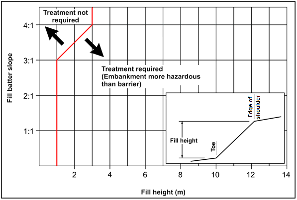
Figure 4.6: Embankment warrant for intermediate and high speed roads
Note:
Based on a comparison of severity indices of batter slope with Type B surface condition (refer Austroads Guide to Road Design Part 6, Table E1) and accepted barriers (refer Austroads Guide to Road Design Part 6, Table E8).
This figure does not consider the likelihood of vehicles encroaching onto the batter and is based on the severities of the embankment and barrier.
(Figure sourced from Austroads Guide to Road Design Part 6: Roadside Design, Safety and Barriers (2009)).
4.3.5 High-consequence Hazards
Various guidelines have been developed in Australasia (e.g. VicRoads) and overseas (e.g. Caltrans in California) for the provision of median barriers on high-speed divided roads. The following guidance is provided for roads controlled by Main Roads WA.
A cross-median crash is strictly defined as one in which an out-of-control vehicle crosses the median of a dual carriageway and strikes, or is struck by, a vehicle from the opposite direction.
Designers should always consider all relevant risk factors that relate to the likelihood of vehicles leaving the road, the associated consequences, and undertake a thorough evaluation.
New or Upgraded Dual Carriageways with posted speed ≥ 100km/h
Median barriers shall be installed on new and upgraded dual carriageways with posted speed limits greater than or equal to 100 km/h, to reduce the incidence of cross-median head-on crashes, where the two-way annual average daily traffic (AADT) using the facility will be greater than 30,000 vehicles per day within 10 years.
Where the AADT will be less than 30,000 vehicles per day within 10 years, a risk assessment should be carried out to assess the need for a median barrier. The risk assessment should include consideration of traffic volume, median width and prior crash history.
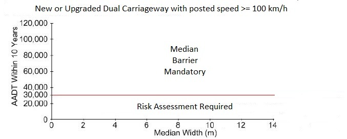
Source: Based on Queensland Department of Transport and Main Roads, Road Planning and Design Manual, 2nd edition, Figure 6.4
New or Upgraded Dual Carriageways with posted speed of 80km/h or 90km/h
Median barriers are recommended to be installed on new and upgraded dual carriageways with posted speed limits equal to 80 km/h or 90km/h, to reduce the incidence of cross-median head-on crashes, where the two-way annual average daily traffic (AADT) using the facility will be greater than 20,000 vehicles per day within 10 years and the median width is less than 10m.
Where the AADT will be less than 20,000 vehicles per day within 10 years or the median width is greater than 10m, a risk assessment should be carried out to assess the need for a median barrier. The risk assessment should include consideration of traffic volume, median width and prior crash history.
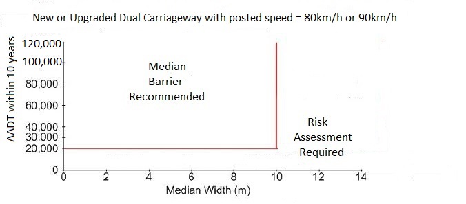
Source: Based on Queensland Department of Transport and Main Roads, Road Planning and Design Manual, 2nd edition, Figure 6.4
New or Upgraded Dual Carriageways with posted speed ≤ 70km/h
A risk assessment should be carried out to assess the need for a median barrier on new and upgraded dual carriageways with posted speed limits of 70 km/h or less. The risk assessment should include consideration of traffic volume, median width and prior crash history.
Risk Assessments for Median Barriers
Risk assessments should be undertaken in accordance with guidance provided in ISO 31000-2009 Risk management – Principles and guidelines.
Risk assessments may include factors such as:
- Whether the median slope is non-recoverable or non-traversable
- Landscaping of the median
- The percentage of heavy vehicles
The investigation of warrants for median barrier is usually only recommended in high speed environments. However, in low speed environments a median barrier might be appropriate:
- Where the roadways on either side of the median are graded independently resulting in a significant height difference and a steep slope across the median, and/or
- For treating sites with pre-existing adverse crash history where median barrier may reduce the severity, if not the frequency, of incidents.
Median Barriers
The type of median barrier selected should take into account:
- The median width and the likely deflection of the barrier when impacted.
- The whole of life costs, including the maintenance requirements.
- The percentage of heavy vehicles and likelihood of an over capacity vehicle breaching the median barrier.
4.3.6 Bridge Guide Banks / Transverse embankments
Bridge guide banks and transverse embankments are a variation of embankments and should be assessed based on the same criteria.
Bridge guide banks are provided at bridge sites to reduce the risk of scour and are protected with rock protection of which class is site specific. Typically if an embankment at a bridge site requires treatment so will any associated guide banks. However, as guide banks are orientated approximately perpendicular to the roadway the severity of an impact by an errant vehicle is different to the embankment situation.
Transverse embankments with relatively flat side slopes may cause vehicular vaulting with the vehicle frequently returning to earth in an adverse landing pattern. For steeper slopes the vehicle bumper may "catch" in the slope resulting in an abrupt stop and high occupant decelerations.
For these reasons, transverse slopes should be as flat as practical.
4.5.6 Detailed Manual Method
This is not to be used for Main Roads WA.
4.5.9 Alternative Crash Risk Method
This method is not to be used for Main Roads WA.
4.6 Hazard Risk Assessment
Sections 4.6.1 – 4.6.4 are not to be used for Main Roads WA. For quantitative evaluation the Queensland Main Roads program Roadside Incident Severity Calculator (RISC) shall be used for undertaking a hazard risk assessment.
The AASHTO Roadside Safety Analysis Program (RSAP) may also be used to provide additional information for assessment. Users should be aware of conditions relating to the outputs of the program.
When undertaking BCR analysis the user shall specify the following crash costs:
- Property
- Moderate injury (medical)
- Hospitalisation
- Fatality
The crash costs to be used shall be obtained from the Road Safety section of the Main Roads Open Data Portal. Main Roads WA does not have costs for minor injury so this is set to zero. The Average Crash Costs by Severity and Region Group is to be used.
The user should consider the benefits of a treatment in treating all of the hazards at the site e.g. installation of a barrier to protect a culvert may also shield existing non-frangible vegetation at the site.
Costs for implementation of the treatment will need to be determined based on the site being considered.
When evaluating barriers and end treatments a 20 year life shall be used.
5. Treatment Options
5.4.5 Treatments for Drains
In addition to the shape of the drain (including drainage basins such as retention and detention basins) consideration shall also be given to the depth of water. Refer to Section 5.4.10 for more information on assessing the depth of water as a hazard.
Where the water depth can reach 1.0 m, or 0.3 m for more than an hour, for the 1 year ARI event then the drain or drainage basin shall be considered non-traversable.
5.4.6 Treatments for Drainage Features
Culverts equal to or less than 900 mm in dia. or box culverts with a span equal to or less than 900 mm can be made safer by the use of a traversable headwall (refer to Main Roads Drawing 200531-0010).
In constrained low traffic situations (less than 150 vehicles per day) it may be acceptable to offset the culvert 1.0 m from the edge of the shoulder providing all of the conditions of Cl 14.5.2 of AS 5100.1 Bridge Design -: Scope and General Principles are met.
Traversable culvert headwalls have higher inlet losses than standard culvert headwalls so are typically less efficient at conveying water under roads. The use of traversable culvert headwalls should only be done with approval from the Road and Traffic Engineering Branch.
Parallel to the Road
Where culverts are placed parallel to the road they can be made safer for road users by installing grating (or rails) over the culverts. Refer to Main Roads Standard Drawing 200531-0010. For this treatment to be effective it must be used on slopes of 1 in 4 or flatter with a pipe diameter or box width less than or equal to 900 mm.”
However, traversable culvert headwalls with grating (or rails) may create ongoing operational and maintenance issues, due to debris collecting in the grating (or rails). The use of traversable culvert headwalls should only be done with approval from the Road and Traffic Engineering Branch.
An acceptable layout for standard culvert headwalls under rural driveways is shown on Main Roads Guideline Drawing 9831-6281.
5.4.8 Treatments for Rock Face Cuttings
The risk of snagging could be reduced by making the cutting smooth for at least the first 1.0 m of the cutting (based on the centre of gravity of a 2000 kg vehicle). This could be achieved in the case of a rock cutting by applying a shotcrete treatment to the cut batters.
The requirement for treatment should be determined on a case-by-case basis depending on the speed environment, traffic volume, offset to the cutting, surface condition and the length of the cutting.
For guidance on the severity of the cuttings refer to the relevant severity indices for different surface conditions in Appendix E.
5.4.13 Treatments for Poles
Slip-base poles
Slip-base poles are designed to operate when impacted at certain speeds. If slip-base poles are installed within the deflection zone of road safety barriers then the slip-base may not operate as intended and the redirection of the vehicle by the barrier may be affected.
For details of slip-base poles refer to Main Roads Standard Drawings 0530-1546 and 0530-1547.
5.4.18 Bridge Piers & Abutments
Bridge piers and abutments should be offset from the road by the dimensions shown on Figure 12.1 of the Bridge Design Information Manual Document No. 3912/02-1 (available from the Main Roads website).
5.4.19 Protection of Pedestrians, Cyclists and Bystanders
In some situations pedestrians or cyclists may be exposed to a higher than normal risk of being struck by an errant vehicle.
For existing sites with a crash history an assessment of pedestrian, cyclist and bystander exposure is required so that crash reductions for a number of alternative treatments can be considered.
The first option to be considered should be relocation of the cyclist / pedestrian facility further from the traffic lanes.
For new works the protection of pedestrians and cyclists from passing traffic also may be considered.
When considering the protection of pedestrians and cyclists at a site the following items should be considered:
- What makes this site more hazardous than other sites along the road?
- What is the number and type of path users (e.g. primary school children)?
- Other benefits of installing a road safety barrier, for example placement of a barrier at an interchange, not only provides protection for pedestrians and cyclists but also protects road users from high embankments, vertical drops associated with bridges and other fixed road infrastructure.
Locations where a barrier may be appropriate are:
- Where a path is within the clear zone for intermediate and high speed roads.
- A heavily trafficked shared use path is separated by less than 4 metres from an adjacent heavily trafficked lane, especially if the geometry is substandard.
- There is expected to be large numbers of bystanders congregated adjacent to the road beyond the clear zone e.g. schoolyard, sporting facilities. If a barrier is to be installed to protect bystanders in this situation, consideration should be given to it being placed closer to the bystanders rather than the road to minimise the potential for vehicle contact.
Main Roads practice is to protect shared or principal shared paths where they are within the clear zone adjacent to intermediate and high speed roads. (i.e. 70km/h or greater)
5.4.20 Rock Spalls and Rock Pitching
The use of rock spalls (large rocks not mortared) within the clear zone is not preferred practice as it can affect the stability of an errant vehicle.
Rock pitching (small rocks mortared in place) providing that the height of the stones above the mortar is less than 50 mm is acceptable within the clear zone.
5.4.21 Separation of Traffic, Transit Corridors and Freight Railways
Barriers may be required to separate through traffic from the following:
- local traffic (e.g. frontage roads)
- opposing traffic
- traffic adjacent to the through traffic where there is a speed differential equal to or greater than 20 km/h
- transit corridors (e.g. busways, railways, light rail etc)
- freight railways
Transit corridors or freight railways within or adjacent to intermediate or high speed roads are typically protected with an appropriate safety barrier unless a comprehensive risk assessment demonstrates that protection is not required. Consideration needs to be given to not only the risk to motorists but also to users of the corridor or the freight railway.
6. Road Safety Barriers
6.1.1 General
For each of the barrier types accepted for use by Main Roads a barrier design sheet has been developed. These sheets contain details on any limitations on the use of the barrier (e.g. proximity to kerbs, minimum lengths) and the accepted configuration.
Main Roads also provides details of work zone barriers.
Main Roads' has developed a Safety Barrier Design Checklist, which is included at Appendix N. Designers should use the checklist to assist in the development of the barrier design.
The process and requirements to evaluate the suitability of a road safety barrier system are specified in Section 4 of AS/NZS 3845.1:2015.
6.3.5 Offset to Travel Lane
Road user requirements
The offset from the edge of travel lane to the face of the barrier should be such that the available stopping sight distance and intersection sight distance are not impeded. It is not possible for drivers to see through roadside barriers.
It is Main Roads preference that the shoulder width adjacent to barriers is at least the same shoulder width as elsewhere along a road.
Barrier setback from kerb
If a W-Beam or thrie-beam barrier must be installed behind kerbing Main Roads preferred option is to place the barrier 200 mm from the face of the kerb. The 200 mm offset minimises nuisance impacts while still reducing the possibility of a vehicle "snagging" under a barrier element.
On kerbed sections of entry and exit ramps with more than one lane, and on kerbed roads with no shoulders and posted speeds ≥ 70 km/h, the offset between the face of kerb and face of W-Beam or thrie-beam barrier shall be increased to 300 mm.
At locations where the lane width is < 3.5 m, increasing the W-Beam or thrie-beam barrier offset from 200 mm to 300 mm is not sufficient and lane widening, or the addition of shoulders, is required. On projects involving new works, the addition of shoulders is preferred.
The offset for WRSB depends on the kerb type adopted and the size of the footing required. Refer to the List of Approved Road Safety Barrier Systems.
Kerbs shall not be placed in front of rigid concrete barriers.
If there is no alternative to placing kerb in front of a barrier, further guidance regarding the position of kerbing is provided in Commentary 12.
The preferred kerbing type adjacent to flexible and semi rigid barriers is Type A 100 mm mountable kerbing. A semi-mountable kerb may be suitable in some situations (typically speeds < 70 km/h).
Barrier type kerbing shall not be used in front of barriers. The different kerb types can be found on Main Roads Standard Drawing 9331-0376.
Shy line offset
While the shy line offset as per Table 6.4 is desirable, it may not be possible to achieve, especially when barriers are retro fitted along a road, without the considerable cost of embankment widening.
Flaring
By adopting a flare the length of barrier required can be significantly reduced. In some situations placing the barrier on a flare may require widening of the road embankment. The additional cost of widening of the embankment should be considered against the extra cost of the barrier and the ongoing maintenance costs.
An amended version of Table 6.5 Flare Rates, below, shall be used in all situations.
|
Design speed (km/h) |
Flare rate for barrier (d:1) |
|
50 |
13:1 |
|
60 |
16:1 |
|
70 |
18:1 |
|
80 |
21:1 |
|
90 |
24:1 |
|
100 |
26:1 |
|
110 |
30:1 |
Table 6.5: Flare Rates
Source (AASHTO Roadside Design Guide 2011)
Guidance for designers on the flaring of barriers at point hazards is provided on Main Roads Guideline Drawing 201531-0080.
Offset to verge barriers
For kerbed roads refer to the information provided in “Barrier setback from kerb” section.
Where barriers are installed on unkerbed roads, the face of barrier should be the same offset as the edge of shoulder. Where a barrier is being retro-fitted this may require embankment widening, which may be costly.
Desirably, verge barriers on high speed, high volume unkerbed roads should be offset sufficient distance from the nearest traffic lane to allow for a broken down vehicle to pull over and for an occupant to get out, while remaining clear of the traffic lane.
To allow for a broken down vehicle to pull over while remaining clear of the traffic lane, verge barriers on unkerbed roads should be offset a minimum of 3.0m from the nearest traffic lane.
Verge barriers on unkerbed roads that are offset less than 3.0 m shall not be greater in length than 500 m, to allow for broken down vehicles to travel to an area where they can pull over clear of the traffic lane.
Verge barriers on unkerbed roads that are offset less than 2.0 m shall not be greater in length than 200 m, to allow for broken down vehicles to travel to an area where they can pull over clear of the traffic lane.
Where road safety barriers are installed along an unkerbed road the shoulder shall be fully sealed so that maintenance of an unsealed shoulder in front of the barrier is not required.
Where a concrete barrier is installed along the verge and the above offsets cannot be achieved, the absolute minimum offset from the edge of the traffic lane shall be:
- 0.3m for a turn pocket or road speed zoned under 70km/h
- 0.6m for a road speed zoned between 70km/h and 90km/h
- 1.0m elsewhere
Offset to median barriers
Typically, the width of median shoulders does not allow for a broken down vehicle to pull over while remaining clear of the traffic lane.
Designers should recognise that in real world situations broken down vehicles will pull over to the median shoulder and block part of the traffic lane. It is recommended that the combined width of the nearest traffic lane and the offset to median barrier is desirably not less than 6.0 m, a width that allows for a slow moving passenger vehicle to travel past a broken down vehicle.
For a traffic lane width of 3.5 m, a desirable minimum offset of 2.5 m to the median barrier is required.
Investigations have shown that on high speed, high volume roads a median barrier offset 1.5 m from the travel lane is impacted more than twice as many times as a median barrier offset 2.5 m from the travel lane. Over the design life, this represents considerable ongoing maintenance costs and risks.
For further information on freeway median barriers refer the MRWA Supplement to the Guide to Road Design, Part 3 Geometric Design – Table 4.3.
Where a concrete barrier is installed along the median and the above offsets cannot be achieved, the absolute minimum offset from the edge of the traffic lane shall be:
- 0.3m for a turn pocket or road speed zoned under 70km/h
- 0.6m for a road speed zoned between 70km/h and 90km/h
- 1.0m elsewhere
Retro fitting of barriers
Where barriers are being retro fitted along verges of an existing road then designers should recognise that in many cases widening of the existing road carriageway is required.
The road carriageway should be sufficient to cater for the:
Support Width (refer to section 6.3.6)
Deflection Width (refer to section 6.3.7) and
System Width (refer to section 6.3.8)
These widths are shown in Figure 6.5a:
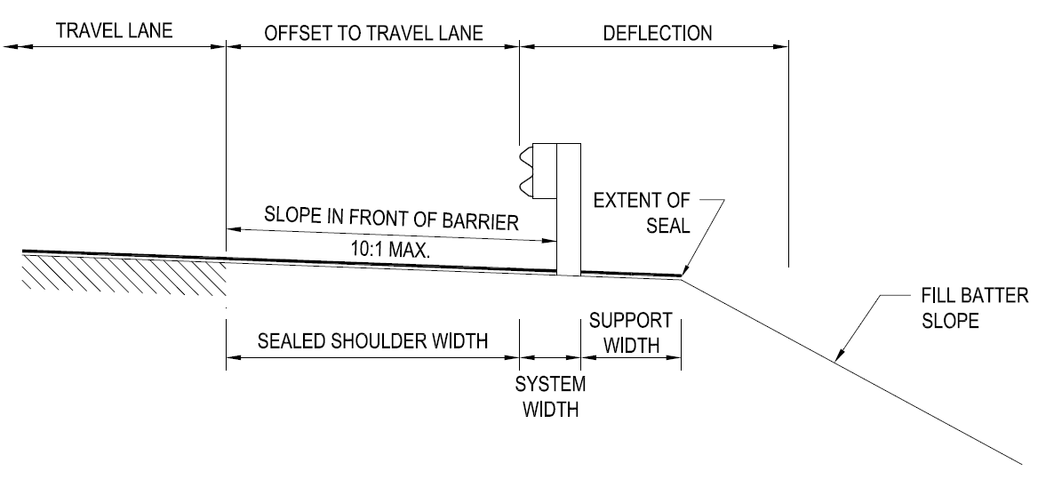
Figure 6.5a: Barrier Width Requirements
Designers should exercise caution if the offset to travel lane is reduced to minimise the cost of retro fitting barriers, as this is likely to result in more nuisance impacts of the barrier, increased ongoing maintenance costs and reduced levels of safety for road users and maintenance providers.
6.3.6 Support Width
The information provided in Table 6.6 is of a general nature and may not be accurate for all cases. For details of the support width required for wire rope safety barriers refer to the manufacturer’s requirements and List of Approved Road Safety Barrier Systems. For W-beam refer to Main Roads drawings 200331-0010, 200931-0002 and 201231-0041.
6.3.13 Step B5 – Determine the Barrier Containment Level Required
The minimum barrier acceptable for use on Main Road's network as a permanent barrier is one capable of restraining a 2000 kg vehicle (if assessed on NCHRP 350 criteria) or a 2270kg (if assessed on MASH criteria) for the proposed design speed.
The question of design vehicle is a critical one that needs to be considered during the design process.
In determining the level of containment the Designer should also consider:
- Consequences of penetration. Are the consequences of a barrier penetration limited to a single vehicle? Or can the consequence of a barrier penetration cause an outcome such as a structure collapse, which may result in a catastrophic outcome?
- Adjacent land use. Are there generators of pedestrians or cyclists such as schools, playgrounds, parks, shopping centres that might increase the probability of an errant vehicle hitting a person? Is the barrier adjacent to railway lines, which may mean a barrier penetration results in a catastrophic outcome?
- Critical infrastructure. Will a barrier penetration result in damage to critical infrastructure, such as power generators, which may cause a catastrophic outcome?
Consideration of these factors may influence the Designer in providing a higher level of protection.
For all barrier designs the Designer shall review available classified traffic count information to determine the % heavy vehicles. If no counts are available for the site then other roads with similar characteristics should be used.
In assessing the classified traffic count information a number of assumptions regarding correlating AS / NZS 3845.1 test vehicles for TL 3, 4 & 5 versus Austroads classes need to be made. These assumptions are:
- TL 3 vehicles are represented by Austroads Classes 1 & 2
- TL 4 vehicles are represented by Austroads Classes 3-5 inclusive
- Combined TL 5 / TL 6 vehicles are Austroads Classes 6-13 inclusive
Where the % of vehicles in TL 4, TL 5 and TL 6 category exceeds 15% then a risk assessment shall be undertaken to determine the design vehicle. An acceptable methodology is that presented in Appendix A of AS 5100.1 with the text in Cl A4.2.5 and Figure A4 replaced with that below.
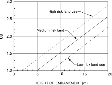
High occupancy land use: refers to land used in such a way that there is a significant risk to persons or property adjacent to the road or significant additional risk to occupants of the errant vehicle e.g. high fill situations adjacent to hospitals, schools, railways, houses etc.
Medium occupancy land use: refers to land used in such a way that there is an occasional risk to persons or property adjacent to the road or additional risk to occupants of the errant vehicle e.g. high fill situations adjacent to other roads with AADT < 10 000 vpd, footpaths, shared use paths or areas with occasional human populations.
Low occupancy land use: refers to land used in such a way that there is a minimal or insignificant risk to persons or property adjacent to the road e.g. open fields, bushland and the like.
In determining the level of protection required Table 6.6(a) shall be used:
|
Level given in Figures A5-A8 |
Replacement Levels |
|
Low level |
TL 3 |
|
Regular level |
TL 4 |
|
Medium |
TL 5 |
Table 6.6(a) Relationship between Barrier Levels in AS 5100 & 3845.1
Alternatively the Designer can undertake their own risk assessment but it shall include a benefit cost approach to the level of protection chosen and shall consider road user costs of impacting with the barrier as well as consequences of the barrier being penetrated.
6.3.14 Step B6 – Choose the Barrier Type
Types of barrier
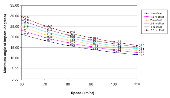
In determining the likely impact angles and the suitability of the barrier types, the Designer shall consider the angle of impact as determined in accordance with Appendix M. In assessing the angle of impact the Designer shall only consider the lane closest to the barrier. For quick reference, a series of charts have been developed based on the methodology contained in Appendix M. Where impact angles including correction for horizontal curvature where appropriate exceed the angles used in crash testing, the Designer shall review the barrier type to confirm that it is still the best alternative.
In the cases of flexible or semi-rigid systems because of the greater angle of impact, it may be necessary to increase the allowance made for deflection. Placing of a barrier at the shyline on a tangential section of road results in impact angles less than or equal to the crash tested angles.
Consideration of occupant impact values should be given when rigid concrete barriers are selected for use in situations of high impact angles (> 20 degrees)
Barrier height
Refer to details under “Height Correction” in the List of Approved Road Safety Barrier Systems for W-beam and wire rope barriers.
Barrier design criteria
When determining the distance in front of hazards that barriers are located, designers are referred to the deflection values published in the Barrier Design Sheets.
Designers should be aware that the deflection values published are the values of test deflections recorded under controlled conditions. The vehicle mass, speed and angle of impact, along with the barrier length and condition are factors that are controlled as part of the testing. Designers should be aware that the deflection figure published as a test result may not be the deflection value achieved in the field for all impacts by errant vehicles.
Barriers across culverts
In setting the test level required for barriers at underpasses and major culverts (those with a span greater than 3m) the procedure given in Step B5 shall be used.
Where there is less than 1 m cover to culverts and or underpasses then normal post and rail systems cannot be used.
Options available to the Designer are:
- Nested W Beam layout as shown on the W-Beam treatment Sheet or drawing 201031-0030.
- Direct connection of the barrier system to the culvert (applicable only for box culverts).
In setting the test level of barrier required, the Designer shall consider the test level of adjacent barriers.
6.3.14.1 Flexible Barrier Systems
Wire Rope Safety Barrier (WRSB)
Wire rope barriers have the highest ongoing maintenance costs, so from an asset management perspective they are not preferred. Designers should be aware of the different components specified for the different wire rope barrier systems and consult with the asset owner prior to specifying these systems.
Along with this consideration, the use of such systems require adequate room to allow for deflection of the barrier and a suitable traversable area over this width of deflection.
For single lane carriageways (i.e. one lane in each direction) where the full verge width cannot be provided due to project constraints a 1m verge is acceptable provided:
1. that the design vehicle is a light vehicle (refer to Section 6.3.13 for guidance on this).
2. slope of this verge is 1 in 10 or flatter. This width should enable at least 2 wheels to remain on the verge for the design light vehicle.
3. that the area behind the barrier to the full width of the dynamic deflection be clear of any fixed hazards and slip base roadside furniture (as these may not work due to the barrier restraining the vehicle) and desirably free of frangible objects.
4. beyond the 1m acceptable verge, embankment slopes are of up to 1 in 4 desirable slope and 1 in 2.5 as the maximum slope.
At anchor locations additional width may be required so as to provide adequate resistance for the anchor block to work during impact. The width requirements for anchor block needs to be in accordance with the manufacturer's published literature.
It should be noted that WRSB have some limitations with regards to horizontal and vertical curves and these systems should be designed in accordance with the manufacturer's published literature.
The amount of deflection expected shall be based on the relevant test level condition (TL 1-TL 3). The deflection shown in the barrier design sheets are based on a single test result achieved under controlled conditions. Deflections of WRSB in real life situations may differ greatly, depending on factors like barrier length and post spacing.
Only tensioned wire rope systems that have been approved by MRWA shall be used. Approved systems are shown in the List of Approved Road Safety Barrier Systems.
The order of magnitude of deflection of these systems is 2.0 m under NCHRP 350 TL 3 conditions (and even greater for MASH TL 3) but is dependent on the actual system used. Expected deflections will depend on factors such as vehicle size, speed, angle of impact and length of barrier. Designers should seek advice from WRSB manufacturers regarding deflection.
All WRSB systems shall be installed with concrete footings / sockets for post installations rather than driven posts as the footing reduces the deflection of the system and also reduces whole of life costing (as during maintenance activities any damaged post can be simply removed from the concrete footing and replaced). For different soil types the size of footing should be confirmed by the WRSB manufacturer. If the post is driven, special plant is required to be mobilised to drive a new post and the time taken to drive the replacement post is longer than simply removing the damaged post from the socket within the concrete footing and inserting a new post.
Water Filled Barriers
Water filled barriers are only to be used as work zone barriers on worksites.
Temporary Steel Barriers
Temporary steel barrier systems are designed to be used as work zone barriers on worksites. Some temporary steel barrier systems may be accepted for permanent use but are likely to have increased maintenance costs, so should only be considered if agreed to by the asset owner. Reference should also be made to the conditions of acceptance of temporary steel barrier systems
6.3.14.2 Semi-rigid Barrier Systems
W-Beam (public domain)
For conditions on its use refer to the W Beam Barrier Design Sheet. Main Roads accepts the use of W-Beam (public domain) on its network to NCHRP 350 TL 3 containment level.
Only the standard components shown on Main Roads Drawing 200331-0013 shall be used with the exception of terminals.
W-Beam (proprietary systems)
A number of proprietary W-Beam barriers have been accepted for use by Main Roads and meet the requirements of MASH TL 3. For conditions on their use, refer to the relevant Barrier Design Sheet.
Designers should be aware of the different components specified for the different proprietary systems and consult with the asset owner prior to specifying these systems.
Thrie-Beam (public domain)
Thrie Beam barriers are acceptable for use in transitions between semi-rigid systems and rigid barriers or in W-Beam terminals.
Main Roads no longer accepts the use of the modified Thrie beam (as detailed on Main Roads Drawing 200331-0017) for new installations.
Thrie Beam (proprietary systems)
A number of proprietary Thrie Beam barriers have been accepted for use by Main Roads and meet the requirements of MASH TL 4. For conditions on their use, refer to the relevant Barrier Design Sheet.
Designers should be aware of the different components specified for the different proprietary systems and consult with the asset owner prior to specifying these systems.
6.3.14.3 Rigid Barrier Systems
Where no deflection can be permitted, or where a higher level of protection is required, a rigid concrete barrier shall be used. The preferred concrete barrier shape is the Californian constant slope barrier. Main Roads also accepts the use the AASHTO "F" shape. Crash testing indicates that both concrete barrier types give a comparable level of performance.
Concrete barriers can be provided to either TL 4 or TL 5 conditions by changing the height of the barrier, footing and reinforcement details.
There is also a vertical wall barrier, which is crashworthy but does result in additional vehicle damage. It is preferable for vertical walls to have one of the concrete shapes on the lower part of the wall to reduce vehicle damage.
AASHTO 2011 provides the following guidance on when the use of vertical wall could be considered; "vertical concrete barrier wall can be an effective alternative to the wider safety-shape barriers and can preserve available median width at narrow locations such as in front of bridge piers.”
When using concrete barriers careful attention needs to be paid to drainage. The use of drainage openings in concrete barriers needs to be carefully considered by the Designer to ensure that the barrier performance is not compromised. The use of any openings in the barrier and any maintenance considerations shall be taken into account.
Refer to the barrier design sheets for more information.
Barriers on Structures
Barriers on bridges shall be provided in accordance with the requirements of the Structures Engineering Branch. The Project Manager shall determine the performance level of the barrier required by consulting the Structures Design & Standards Engineer (SDSE).
Careful attention needs to be given to the extent of barrier required on the approach and departure of the bridge to a roadside barrier system to ensure that the vertical drop associated with the bridge and associated wingwalls as well as any roadside hazards (e.g. fill embankments or objects) are adequately protected.
The same level of protection provided on the bridge shall be provided on the approaches for a length necessary to adequately protect the hazard where consequences of the barrier being penetrated are similar to that of the bridge barrier being penetrated. Only when the hazard is adequately protected should the level of the barrier be reduced.
An acceptable methodology to determine the length of barrier required is that presented in Appendix B of AS 5100 with the modifications outlined in Section 6.3.13.
The designer shall at increments away from the bridge undertake the process outlined in Appendix B of AS 5100 to determine where or if the level of the barrier can be reduced.
Refer to Main Roads drawing 200531-0005 for guidance on the treatment of barriers at interchanges.
6.3.15 Step B7 – Determine Dynamic Deflection
The amount of deflection for certain types of barriers, measured under controlled crash test conditions is given in the barrier design sheets. No hazard, including rigid or frangible objects, paths or non-traversable slopes should be placed within the width required to accommodate the dynamic deflection of the barrier.
6.3.16 Step B8 – Determine Vehicle Roll Allowance and System Width
Vehicle roll allowance shall be determined and allowed for when barriers rated TL4 and greater are used (i.e. barriers designed to contain high vehicles).
The values given in Table 6.8 are not accepted.
The vehicle roll allowance for non-rigid barriers shall be as per the working width specified for each barrier.
For rigid barriers, the “Zone of Intrusion” concept as described in Section 5.5.2 of the AASHTO Roadside Design Guide 2011 shall be applied.
The Zone of Intrusion (ZOI) is the region measured above and behind the face of a barrier system where an impacting vehicle or any major part of the system may extend during an impact.
Based on Figure 5-31 of the AASHTO Roadside Design Guide 2011, the following figures shall be used by designers to determine the ZOI:

Figure 6.20a: Zone of Intrusion for TL4 Rigid Barrier
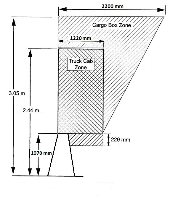
Figure 6.20b: Zone of Intrusion for TL5 Rigid Barrier
6.3.19 Step B11 – Determine Barrier Points of Need
Main Roads uses the run-out length method for the calculation of barrier length.
The angle of departure method shall not be used.
An amended version of Table 6.9 Run-out Lengths for Barrier Design, below, shall be used in all situations.
In constrained situations the run-out length used to determine the location of the points of need may be reduced, on the basis of cost benefit analyses. This should only be used with the approval of Main Roads.
|
Design Speed (km/h) |
Run-out Length LR (m) for AADT range |
|||
|
|
10,000+ |
5,000 to <10,000 |
1,000 to <5,000 |
< 1,000 |
|
110 |
110 |
101 |
88 |
76 |
|
100 |
91 |
76 |
64 |
61 |
|
90 |
80 |
67 |
56 |
54 |
|
80 |
70 |
58 |
49 |
46 |
|
70 |
60 |
49 |
42 |
38 |
|
60 |
49 |
40 |
34 |
30 |
|
50 |
34 |
27 |
24 |
21 |
Table 6.9: Run-out Lengths for Barrier Design
Source: (AASHTO Roadside Design Guide 2011)
The statement that the run-out length (LR) “is the theoretical distance needed for a vehicle that has left the roadway to come to a stop” is not supported by Main Roads WA.
6.3.22 Step B14 – Choose Terminal Treatments
For guidance on the alignment and grading required for various W-beam end treatment options refer to Main Roads Drawing 201531-0096 and 201531-0097.
Only terminals that have been approved for use by Main Roads shall be used. A list of these terminals and restrictions on their use can be found on the end treatment design sheets, which is attached to the List of Approved Road Safety Barrier Systems.
Where kerbing is present at the site and the type is to be modified for the barrier then the modification shall be extended upstream of the terminal to a point determined where an errant vehicle would cross the kerb line at 1 in 20 measured from the start of the terminal.
In some locations (such as at interchanges with local roads) it may not be possible to comply with all recommended practices and the Designer may need to make judgements as to which aspects of the design need to be compromised in order to develop an acceptable solution. In developing an acceptable solution additional costs should not be used as a trade off against safety.
In addition to the crash cushion and impact attenuator factors contained within the Austroads Guide for the design of crash cushion and impact attenuators the following shall also be considered:
- Kerbs and pavement elevations - To reduce the likelihood of a vehicle vaulting there should be no kerbs or islands for a distance of at least 16 m in front, or to the rear of the unit. When it is necessary to place a kerb then a mountable kerb of no more than 100 mm in height shall be used. Delineators and signs should be relocated behind the unit.
- Angle of probable impact - If the hazard is located on a horizontal curve or where two roadways diverge (gore area) then the probable impact angle should be determined as this may be a factor in unit selection.
- Site features - Determine if there are unique features that may affect the positioning or performance of the unit. For example, expansion joints on bridges and drainage inlets may require modifications to ensure that the expansion joints do not compromise the tension of redirecting cables, or that the unit itself does not restrict water flow.
- Orientation - The unit should be orientated to accommodate the probable impact angle of an errant vehicle. This will maximise the likelihood of a head on impact and proper operation of the crash attenuator. This orientation is not as important for crash cushions that have redirective capabilities. The desired orientation angle will depend upon the design speed, roadway alignment and lateral offset to the device. A maximum angle of 10 degrees between the longitudinal centre line of the roadway and the crash attenuator is often considered as appropriate.
A checklist for the design appears in Appendix O.
6.3.23 Step B15 – Design the Transitions Between Barriers
Add the following section.
6.3.23.1 Typical Interfaces between Barrier Types
W-Beam to Concrete
Main Roads drawing 200331-0022 shows transition details from a rigid barrier to W beam.
Transitions from Road Safety Barriers to Traffic Barriers for Structures
Main Roads Drawings 0430-0765 & 0430-0766 shows transition details from a W beam barrier to Regular Level traffic barrier for structures.
Main Roads Drawings 0430-0770 & 0430-0771 shows transition details from a W beam barrier to Low Level traffic barrier for structures.
6.7.1 Barriers at Intersections
When a W Beam system is installed around a curve the posts shall be weakened as per Figures L1 and L2 (in Appendix L) providing that a flat area graded at 1 in 10 or less free of fixed hazards can be provided.
If these criteria cannot be met then a non-weakened barrier is to be installed.
The use of the weakened W Beam is more critical at locations where speeds are greater than 80 km/h.
6.7.5 Deliniation
Delineators shall be placed on road safety barriers in accordance with Australian Standard AS 1742.2-2009 “Manual of Uniform Traffic Control Devices, Part 2: Traffic Control Devices for General Use”. Departures from this document are described in this section.
Rigid & Semi-Rigid Barrier Systems
The spacing of delineators on rigid & semi-rigid barriers shall be:
- Where barrier is >4m from the edge of traffic lane – no delineators placed on the barrier, guide posts provided at spacing as per Clause 5.2 of Main Roads WA Design of Guide Posts.
- Where barrier is between 2m and 4m from the edge of traffic lane – delineator spacing as per Clause 5.2 of Main Roads WA Design of Guide Posts to a maximum spacing of 20m. A delineator shall also be placed at the beginning and end of each barrier length.
- Where barrier is closer than 2m from the edge of traffic lane – maximum delineator spacing of 4m on curves of 100m radius or less, or 8m maximum spacing elsewhere.
The size of the retro-reflector on the delineator shall be a minimum of 100cm2. The delineator shall be attached to the barrier as per the manufactures specifications and so that it protrudes above the top of the barrier. For motorcyclist safety, ensure delineators are frangible and not sharp.
No additional holes shall be made in the posts of the public domain semi-rigid barriers.
Flexible Barrier Systems
The spacing and size of delineators on flexible barrier systems is as per the relevant Main Roads design sheets in the List of Approved Road Safety Barrier Systems.
Type & Colour
The retro-reflector shall contain Class 900 retro-reflective sheeting complying with the requirements of Class 900 material as defined in AS 1906.1.
As per AS 1742.2-2009, the colour of the retro-reflector on the delineator shall be as follows:
• Red – on the left side of the roadway
• White – on the right side of two-way roadways i.e. single carriageway.
• Yellow – on the right side of one-way roadways i.e. dual carriageways (including divided roads).
7. Design for Steep Downgrades
Further information on arrester beds, including design aspects and operational procedures can be found in Design of Truck Arrester Beds.
8. References
- Austroads Guide to Road Design, Part 6: Roadside Design, Safety and Barriers (2009)
- Austroads Guide to Road Design Part 3: Geometric Design (2009).
- AASHTO Roadside Design Guide (2011)
- AS 5100.1 Bridge Design Part 1: Scope and General Principles (2004)
- AS/NZS 3845.1:2015, Road safety barrier systems and devices Part 1: Road safety barrier systems
- Transportation Research Board, NCHRP Report 350, Recommended Procedures for the Safety Performance Evaluation of Highway Features (1993)
- American Association of State Highway and Transportation Officials (AASHTO), Manual for Assessing Safety Hardware (MASH), 2009
9. Appendix
Appendix C – RTA Method
This method is not to be used for Main Roads Western Australia.
Appendix D – Examples of Clear Zone Calculations
D.2 Example 2
Discussion
A quantitative assessment of the risk associated with the hazards caused by the trees and by the installation of a road safety barrier should be undertaken.
Appendix E – Severity Indices Table
An Excel version of the Severity Indices referred to in Appendix E can be accessed by clicking the link below:
Table E 8: Suggested severity indices – traffic barriers
The “Object type and characteristics” describes road safety barriers in terms and configurations that are used in the United States. Designers should be aware that these terms and configurations may differ significantly from those used in WA. For example, under “Longitudinal traffic barriers – Uniform section” the following two barrier types are included:
|
Non-blocked out W-beam on strong posts with 1.9m post spacing.
|
W-beam barrier approved for use by Main Roads WA requires blockouts. |
|
Cable on strong posts
|
This barrier type consists of untensioned wire rope between strengthened posts, while the wire rope safety barriers used in WA consist of tensioned wire ropes between posts. |
Appendix G – RISC Method and Process
The user factor EF should not be used without approval from Main Roads WA.
Appendix H – Treatments for Brownfield Sites
H.3.1 Location on Embankments
Road safety barriers are not to be installed on batter slopes steeper than 10:1 unless approved by Main Roads.
Appendix I – Examples of Length of Need Calculations
I.3 Angle of Departure Method
This method is not to be used for Main Roads.
I.4.1 Example 1
Note that a flare rate of 1:18 was selected for this example. From Table 6.5, the 1:18 flare rate (at 100km/h design speed) applies to a rigid barrier outside the shy line. In this example a flare rate as steep as 1:14 could have been used, as a W-beam barrier (i.e. a non-rigid barrier) was being used.
On page 212, delete:
“X for leading point of need = (6.0-2.8)/(6.0/130) = 53.3m”
And replace with:
“X for leading point of need = (6.0-2.8)/(6.0/130) = 69.3m”
On page 212, delete:
“= 53.3 + 6 + 43.8 = 103.1m”
And replace with:
“= 69.3 + 6 + 43.8 = 119.1m”
On page 212, delete:
“Allowing for two terminals the overall length of barrier for Line B may be about 220 m.”
And replace with:
“Allowing for two terminals the overall length of barrier for Line B may be about 119 + 11 = 130 m.”
On page 212, delete:
“In summary, a barrier that allows for flaring of both ends would be 66 m long between points of need and a barrier that is not flared at the ends would be 103 m long between points of need.”
And replace with:
“In summary, a barrier that allows for flaring of both ends would be 66 m long between points of need and a barrier that is not flared at the ends would be 130 m long between points of need.”
Note that in Figure I4, the dimension shown as “103m” should be “130m” and that the leader for the 66m dimension is incorrectly shown.
I.4.2 Example 2
On page 216, delete:
“Referring to Table 6.4 the shy line for the right side barrier on a 110km/h road is 2.0 m from the edge of the traffic lane.”
And replace with:
“Referring to Table 6.4 the shy line for the right side barrier on a 110km/h road is 2.8 m from the edge of the traffic lane.”
On page 216, delete:
“b = 1 Table 6.4, shy line is 2.0 m from traffic lane and road safety barrier is 1 m within the shy line. From Table 6.5 flare rate b:a is 1:30”
And replace with:
“b = 1 Table 6.4, shy line is 2.8 m from traffic lane and road safety barrier is 1.8 m within the shy line. From Table 6.5 flare rate b:a is 1:30”
Appendix J – Types of Safety Barrier Terminals
For details of terminals approved for use by Main Roads WA, refer to the List of Approved Road Safety Barrier Systems.
Appendix K – Transitions Between Barrier Types
K.4 W-beam to Thrie-beam
Refer to Main Roads standard drawing 200331-0019
K.5 W-beam to Concrete
Refer to Main Roads standard drawing 200331-0021
K.6 Thrie-beam to Concrete
Refer to Main Roads standard drawing 200331-0022
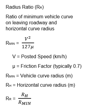
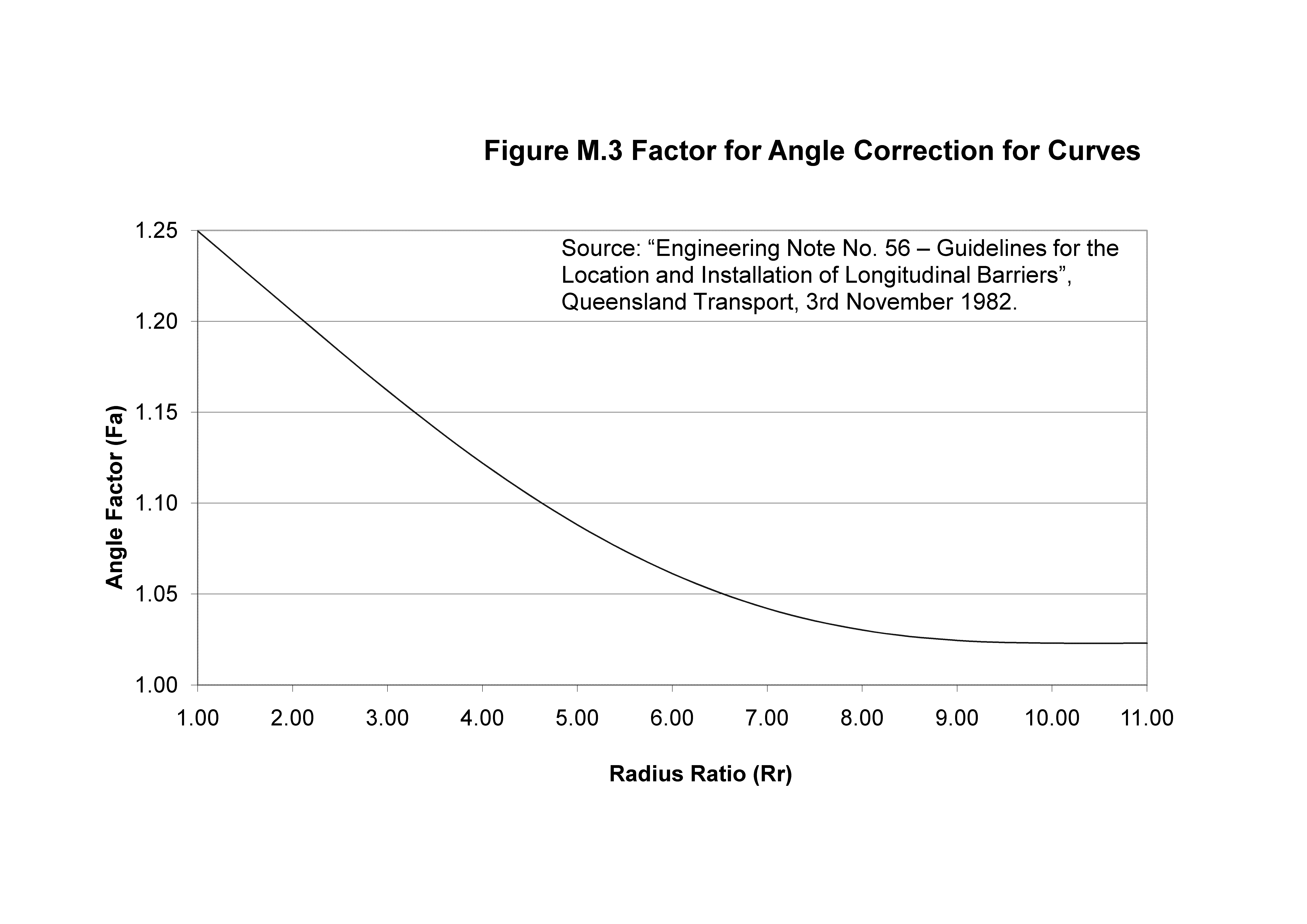
Appendix M - Angles of Impact
The likely angle of impact for straight road sections can be determined from the equation in Figure M1 or the graph in Figure M2.
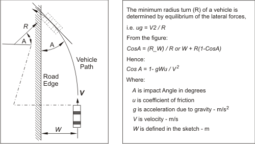
Figure M1: The source of this figure is Figure A.5 “Encroachment Angle Model” AASHTO Roadside Design Guide 1996
If the road is on a horizontal curve, calculate the Radius Ratio from the below equation and determine the Angle Factor from Figure M3. Multiply the equivalent ‘straight’ angle from Figure M1 or M2 by the Angle Factor to get the likely impact angle under horizontal curve conditions.
Appendix N – Safety Barrier Design Checklist
|
Project: ......................... |
Project No: ............... |
Road Safety Barrier Type: ................. |
|
Project Manager: .................................................. |
Date:................................................. |
|
|
Site Information |
Comment |
|
General site details |
|
|
Existing clear zone dimensions |
|
|
Provisions for access - pedestrians, traffic etc |
|
|
Spacing etc of access through RSB system for emergency or other uses |
|
|
Terrain Effects |
|
|
At approach to leading end (restrictions on the use of gating terminals) |
|
|
Along barrier length |
|
|
On departure end treatment |
|
|
Possible restrictions on post lengths (services) |
|
|
Other hazards on site - drainage, non-frangible power poles etc |
|
|
Existing delineation at site |
|
|
Flooding |
|
|
Other site information |
|
|
Compatibility with other adjacent roadside barriers |
|
|
Aesthetic Considerations |
|
|
Will proposed barrier restrict sight distance |
|
|
Site crash history |
|
Design Inputs |
Comment |
|
Existing traffic type - % Class 1 and 2 |
|
|
Existing traffic type - % Class 3, 4 and 5 |
|
|
Existing traffic type - % Class 6 and over |
|
|
Design Vehicle proposed |
|
|
Site Operating Speed |
|
|
Design speed and angle |
|
|
Impact Angle |
|
|
RSB Test level proposed |
|
|
RSB Information |
|
|
Location - start and end, length |
|
|
Minimum offset from adjacent traffic lane (Shy line offset) |
|
|
Allowable dynamic deflection and working width restrictions |
|
|
Nature of ground for structural support |
|
|
Leading End Treatment chosen |
|
|
Departure end treatment chosen |
|
|
Other road furniture to be incorporated into RSB |
Appendix O - Crash Attenuator Design Checklist
|
Date of Design / Inspection if existing hazard
Designed / Inspected By Location Road Name SLK |
|
|
LOCATION OF HAZARD |
|
|
Roadside |
|
|
Median |
Width (m) |
|
HAZARD CHARACTERISTICS |
|
|
Width |
|
|
SITE / DESIGN CONSIDERATIONS |
|
|
Note any site considerations for a distance of 150m in front and immediately to each side of the hazard. |
|
|
Attach photographs if existing site. |
|
|
Do kerbs exist? |
Type |
|
Height |
|
|
Design Speed |
(km/h) |
|
Traffic |
Uni-directional |
|
Bi-directional |
|
|
Average traffic volume (two way volume): |
|
|
Heavy truck traffic: |
% |
|
Vertical Grade % |
% |
|
Cross slope % |
% |
|
Deck/Structure |
Expansion Joints Present: Yes / No |
|
Base type |
|
|
Concrete Thickness |
|
|
Asphalt |
|
|
Soil |
|
|
Back-up Type to be used |
|