Design of Guide Posts
Table of Contents
1. Purpose
Guide posts and delineators shall be placed in accordance with Australian Standard AS 1742.2-2009 "Manual of Uniform Traffic Control Devices, Part 2: Traffic Control Devices for General Use".
Departures from the above reference documents are described in this guideline.
For technical specifications on types and installation requirements of guide posts and delineators refer, to Main Roads' Technical Specification 602 Guide Posts.
2. Use
Guide posts with delineators shall be placed in accordance with this guideline.
Where "all night" street lighting is provided, guide posts are not required. Where street lighting is routinely turned off during the night, guide posts shall be provided.
To maintain visual uniformity there shall be consistency of guide posts types and delineators, longitudinally and laterally within sections of road. It is Main Roads practice that:
- Sections of road installed with the same delineator type must be at least 2 km long.
- Changes from one delineator type should occur on tangents and not horizontal curves.
- Delineators must be of the same type on both sides of the road.
An exception to all of the above would be when there is a barrier on one side and the barrier has delineators attached.
On bridge barriers and road safety barriers, delineators shall be located and spaced as per AS1742.2-2009, Clause 4.2.5.4 (b).
Guide posts are not usually provided at driveways.
3. Delineators
3.1 Delineator Types
Main Roads uses white, yellow and red delineators, conforming to the following two types of reflective materials
Type A (Corner cubed delineator)
- A 80 mm diameter plastic disk.
- Retroreflective Materials as per AS 1906.2-2007 “Retroreflective Materials and Devices for Road Traffic Control Purposed, Part 2 Retroreflective Devices (Non-Pavement Application)”.
- These delineators are susceptible to impact damage when the guide post is hit.
- Type A delineators should not be used on flexible guide posts.
Class 1A Retroreflective Delineator
- Class 1A material as per AS 1906.1-2007 “Retroreflective Materials and Devices for Road Traffic Control Purposes, Part 1 Retroreflective Sheeting”.
- Supplied in adhesive sheet form.
- Size 200mm by 50mm.
- These delineators are less susceptible to impact damage when the guide post is hit.
Class 1 retroreflective sheeting delineators are no longer used by Main Roads due to poor photometric performance.
3.2 Location of Delineators
As per AS 1742.2-2009 Clause 4.2.5.2, the following colours shall be used for the purpose described below:
- White
On the right side of two-way roadways i.e. single carriageway.
- Yellow
On the right side of one-way roadways i.e. dual carriageway (including divided roads).
- Red
On the left side of the roadway.
Refer to Figure 1, 2, 3 for an illustration of the above.
4. Position
On unkerbed roads, the guide posts shall be offset up to 200mm outside the edge of shoulders, within the batter slope, with the delineators facing the direction of oncoming traffic. The required offset shall be determined by the Regional Asset Manager.
For visual uniformity, on unkerbed roads, sections of road where guide posts are installed shall have a consistent offset from the edge of shoulder and shall be at least 2km long.
For dual carriageways separated by a median, guide posts shall be located on both sides of each carriageway, with delineators facing the direction of oncoming traffic.
Refer to Figures 1, 2 and 3 for Main Roads practice of locating guide posts and delineators.

Location of Guide Posts and Delineators
on Single Carriageways
Figure 1
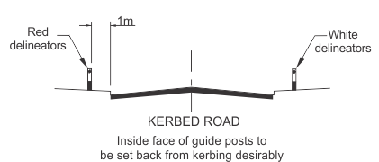
Location of Guide Posts and Delineators
on Kerbed Roads
Figure 2
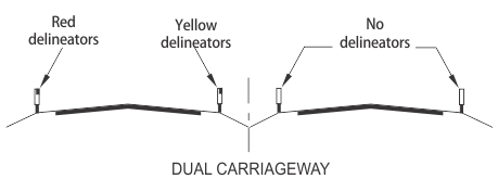
Location of Guide Posts and Delineators
on Dual Carriageways
Figure 3
5. Guide Post Spacing
The spacing of guide posts shall be in accordance with AS 1742.2-2009 and Clause 5 of this guideline. The guide posts are placed on both sides of the road.
Additional guide posts and culvert posts shall then be placed at culvert locations as per Clause 5.5. If a culvert is located within 15m of a normal guide post location, the guide post spacing should be adjusted to match with the culvert site.
5.1 Straights
- Along straights, spacing of guide posts and delineators shall be either 150 metres or a maximum of 300 m as per Australian Standard 1742.2-2009 Clause 4.2.4.4(a).
- For roads with an AADT of less than 50 vpd, guide posts may be omitted on straights but not at crests, bridges, culverts and floodways.
5.2 Curves
Spacing of Guide Posts on curves shall be in accordance with the following Table:
|
Curve Radius |
Spacing (meters) |
|
|
On outside of curve |
On inside of curve |
|
|
<100 |
6 |
12 |
|
100 - 199 |
10 |
20 |
|
200 - 299 |
15 |
30 |
|
300 - 399 |
20 |
40 |
|
400 - 599 |
40 |
40 |
|
600 - 799 |
50 |
50 |
|
800 - 1199 |
60 |
60 |
|
1200 - 2000 |
90 (Note 2) |
90 (Note 2) |
|
> 2000 |
150 |
150 |
Spacing of Guide Posts
Table 1
NOTES:
- Where the radius of an existing curve is not available from records, it may be determined approximately by measuring the middle ordinate offset from a chord of known length using either the edge of pavement or a marked longitudinal line as a guide.
- Spacing is reduced to 75m in areas subject to fog. (See AS 1742.2-2009, Clause 4.2.4.4 (a)).
- Guideposts shall be placed on both sides of the road at the start and finish of the curve.
5.3 On Curve Transitions
Guide posts on curve transitions shall be placed in accordance with Clause 4.2.4.4 (c) of AS 1742.2-2009.
5.4 Crests
On crests, guide posts shall be arranged so that the delineators on at least two pairs of guide posts are visible at all times to a driver, excluding any posts that are less than 40m ahead of the driver. Refer to Figure 4.
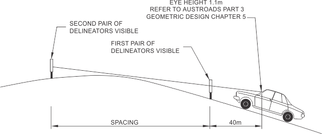
Spacing of Guide Posts on Crests
Figure 4
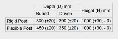
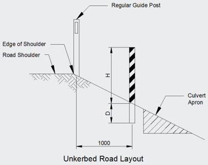
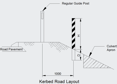
5.5 Bridges and Culverts
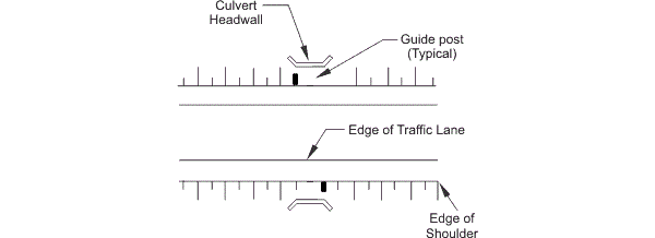
Main Roads requirements are that guide posts shall be placed at culverts where the headwalls are located less than 3 m from the outside edge of the shoulder. This may be the sealed edge of shoulder only where no unsealed shoulder exists.
Some examples are diagrammatically shown in Figures 5, 6, 7 and 8:
For structures > 5m in width Spacing of Guide Posts at Bridges & Culverts
Figure 5
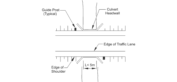
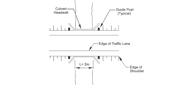
For structures < 5m in width Spacing of Guide Posts at Bridges & Culverts
Figure 6
Where outside edge of shoulder to headwall is < 3m Spacing of Guide Posts at Single Barrel Culverts
Figure 7
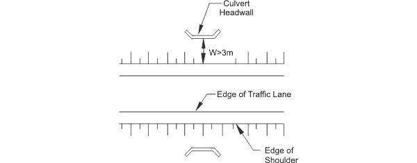
Where outside edge of shoulder to headwall is > 3m - no Guide Posts Spacing of Guide Posts at Culvert Structures
Figure 8
5.5.1 The Use of Culvert Posts to Mark Culvert Headwalls (optional)
The use of culvert posts is optional. Culvert posts are intended to highlight the location of a culvert headwall.
The following recommendations are proposed to ensure consistency in the application of culvert posts in marking out of culvert headwalls.
- A culvert post is to be the same length and width as a standard guide post, has no delineators and consist of black and white stripes placed diagonally at an angle of 45°. Refer to Figures 9 and 10 for details of a culvert post and its location. For further details refer to Main Roads drawing 201331-0007 Hazard Markers.
- The culvert post is to be selected from the approved guide post in Specification 602 and shall be marked in accordance with this Clause.
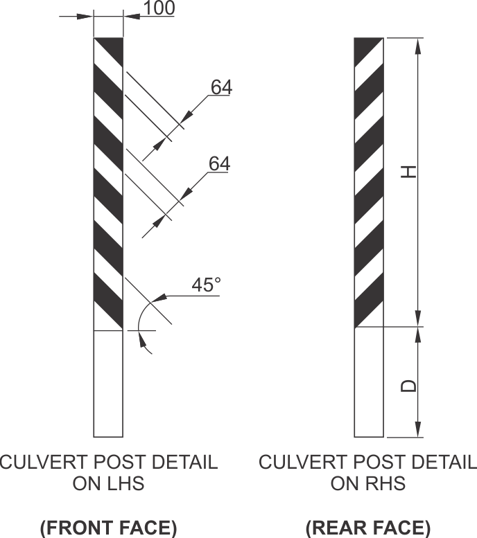
Culvert Post Detail
Figure 9
Culvert Post Location
Figure 10
- The culvert post is to be placed 1.0m outside the line of the guide posts. Please note, as per AS 1742.2, guide posts are still required to be placed at culvert sites which warrant them. Refer to Figure 10 for details.
- Please note, as per current Main Roads practice a bridge width marker shall be installed if a culvert headwall is within the shoulder.
Below is an outline for determining the location of guide posts and culvert posts. For a diagrammatic description refer to Figure 11.
Step 1-
Regular guide posts (black dots) are positioned at key points i.e. end of curves. Spacing between these points is divided to provide a uniform spacing of guide posts as specified in Clause 5.2 Table 1 of this guideline.
Step 2-
Additional guide posts are added at culvert sites (blue dots), as per Clause 5.5 of this guideline.
Step 3-
If required, culvert posts (red dots) shall then be placed 1.0m outside the line of the guide posts at culvert sites.
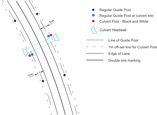
Positioning of Culvert Posts
Figure 11
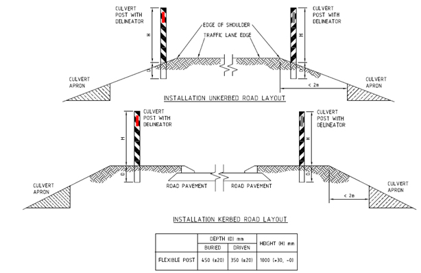
5.5.2 The Use Of Culvert Posts With Guide Post Delineators At Culvert Headwalls (Optional)
The culvert post with delineators are intended to highlight the location of a culvert headwall and to mark edge of road formation. Either a culvert post with a regular post, (refer to Figures 10 and 11) or a culvert post with delineators, refer to Figure 11A, shall be used to highlight location of culvert headwall.
On unkerbed roads, a culvert post with a regular guide post, (refer to Figures 10 and 11) shall be used where culvert headwall is located more than 2m from the edge of shoulder.
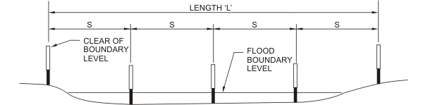
5.6 Floodways
A pair of guide posts shall be placed clear of the flood boundary level at each end of the floodway.
Main Roads practice is that guide posts shall be positioned along the outer edge of the constructed floodway, refer to Figures 12, 13 and 14.
A pair of guide posts shall be provided approximately every 25m (maximum) over the length of the floodway (L) to delineate the edge of the road pavement.
In addition to guide posts there should also be installed floodway depth indicators in accordance with AS 1742.2-2009, Section 4.10 Water Crossings and Main Roads Guideline Drawing 201331-0045.
Spacing of Guide Posts along Floodways
Figure 12
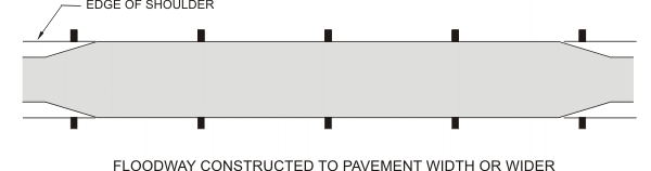
Figure 13
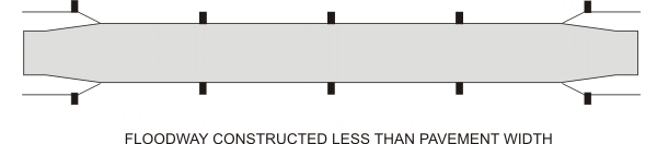
Figure 14
5.7 Merge Tapers
Guide posts are to be placed along the length of the merge taper at a spacing of 24m (Refer to Main Roads WA Standard drawings 200631-0039 and 201431-0021).
6. References
Australian Standards
1742.2-2009 Manual of Uniform Traffic Control Devices - Traffic Control Devices for General Use
1906.1-2007 Reflective Materials and Devices for Road Traffic Control Purposes - Reflective Materials
1906.2-2007 Reflective Materials and Devices for Road Traffic Control Purposes - Reflective Devices (non pavement application)
Main Roads WA Technical Specification "602 Guide Posts"