Guide to Design of Oversize and Over-Mass Vehicle Corridors
Table of Contents
- 1. Contacts
- 2. General
- 3. Policy
- 4. Definitions
- 5. General Standards and Applications
- 6. Design Criteria
- 6.1 General
- 6.2 Design vehicles
- 6.3 Design Vehicle Swept Paths
- 6.4 Road Widths
- 6.5 Median Central and Left Turn Islands
- 6.6 Clearances
- 6.7 Grade Separation
- 6.8 Grades and Superelevation
- 6.9 Other Road and Traffic Engineering Standards
- 6.10 Bridges and other Structures
- 6.11 Pavement and Surfacing
- 6.12 Other Considerations
- 7. Services
- 8. Traffic Management
- 9. Appendices
1. Contacts
| Section of Guideline | Responsibility area and contact details |
| 1,2,3,4,5 |
MRWA - Road and Traffic Engineering (RTE) |
| 6.1 | MRWA - Heavy Vehicle Services (HVS) Contact: rich.bain@mainroads.wa.gov.au |
| 6.2, 6.3, 6.4, 6.5 | MRWA - Road and Traffic Engineering (RTE) Contact: nick.delamotte@mainroads.wa.gov.au |
| 6.6 |
MRWA - Heavy Vehicle Services (HVS) MRWA - Road and Traffic Engineering (RTE) |
| 6.7, 6.8, 6.9 | MRWA - Road and Traffic Engineering (RTE) Contact: nick.delamotte@mainroads.wa.gov.au |
| 6.10 | MRWA - Structures Engineering Branch (SE) Contact: raquib.hossain@mainroads.wa.gov.au |
| 6.11 | MRWA - Materials Engineering Branch (MEB) Contact: elsabe.vanaswegen@mainroads.wa.gov.au |
| 6.12 | MRWA - Road and Traffic Engineering (RTE) Contact: nick.delamotte@mainroads.wa.gov.au |
| 7.1 | Western Power Contact: oversize.loads@westernpower.com.au |
| 7.2 | MRWA - Structures Engineering Branch (SE) Contact: raquib.hossain@mainroads.wa.gov.au |
| 8.1, 8.2, 8.3, 8.4 |
MRWA - Road and Traffic Engineering (RTE) MRWA - Heavy Vehicle Services (HVS) |
| Appendix A | MRWA - Heavy Vehicle Services (HVS) Contact: rich.bain@mainroads.wa.gov.au |
| Appendix B, Appendix C | MRWA - Road and Traffic Engineering (RTE) Contact: nick.delamotte@mainroads.wa.gov.au |
| Appendix D | Western Power Contact: oversize.loads@westernpower.com.au |
2. General
The following criteria define the design standards needed to satisfy efficient movement of Oversize Over-Mass (OSOM) vehicles.
OSOM corridors involve the development of suitable transport routes to accommodate large indivisible loads along the designated OSOM corridors outlined in Section 5.1 linking key heavy fabrication centres and the Australian Marine Complex in the Perth Metropolitan area with mine sites, refineries and other industrial factories that require large machinery and plant. The clearances required for OSOM corridors are specified in Section 6.6 Clearances. While the OSOM corridors cater for the larger OSOM vehicles, consideration also needs to be given to providing connectivity between key areas and the OSOM corridors.
3. Policy
Main Roads supports the provision of OSOM corridors in WA to improve the efficiency and competitiveness of industry and ultimately the State's economy and also the safety and efficiency of the road network.
All future road works (including pedestrian overpasses) and power line work on designated OSOM routes should take into account the OSOM requirements.
4. Definitions
|
Term |
Definition |
|
Oversize Over-Mass (OSOM) vehicles |
An OSOM vehicle is any Restricted Access Vehicle carrying, or designed to carry, a large indivisible load and exceeds a statutory mass or dimension limit, i.e. exceeds the requirements for an ‘As-of-right Vehicle’.
Typically, an OSOM vehicle that together with its load, can have the following dimensions and mass:
OSOM vehicles may have lesser dimensions on routes providing connectivity to the OSOM corridors and in some instances, the OSOM corridors may provide for greater dimensions. Heavy Vehicle Services (HVS) manage OSOM access through a system of permits and orders in accordance with State legislation.By definition, Oversize Over-Mass (OSOM) are Restricted Access Vehicles. |
|
Restricted Access Vehicle (RAV) |
A vehicle is classed a Restricted Access Vehicle (RAV) if that vehicle alone or together with any load exceeds one or more of the following limits:
|
5. General Standards and Applications
5.1 Oversize Over-Mass Corridors
The Oversize Over-Mass vehicle Corridors that link key heavy industry centres and the Australian Marine Complex, in the Perth Metropolitan area are shown in the Main Roads HVS Network Map Tool. While the width and height requirements may vary, the mass requirements are consistent for all corridors.
When undertaking future road works (including pedestrian overpasses) and power line work on designated OSOM routes, consideration should be given to the OSOM requirements. This should be done in consultation with Main Roads – Road Planning Branch as well as Main Roads - Heavy Vehicle Services.
When undertaking future road works and power line work on other roads, consideration should also be given to whether or not the particular road provides connectivity between an industrial area or port, where OSOM vehicles may require access. Main Roads Heavy Vehicle Services should be consulted to provide advice on the size of OSOM vehicles that road works and power line works should accommodate on roads that do not form part of the OSOM corridors.
Oversize Over-Mass Corridors can be located using the Main Roads HVS Network Map Tool.
6. Design Criteria
6.1 General
The following criteria is to be applied to new roadwork and power line modifications on OSOM corridors. Existing infrastructure that can accommodate the absolute minimum clearance requirements (refer to Section 6.6) without alteration need not be modified to meet the design criteria. Any alteration should be based on the desirable minimum clearance requirements as per Section 6.6 Clearances.
6.2 Design vehicles
Three vehicles or approved equivalents have been nominated to carry OSOM loads. The configuration of these vehicles is shown in the diagrams in Appendix B.
- Drake 20 row 'Two File' at 1.80 m axle spacing and 3.70 m spread, and overall length of 50.84 m;
- Nicolas 22 row 'Two File' at 1.55 m axle spacing and 2.99 m spread, and overall length of 46.50 m and;
- Nicolas 16 row 'Side by Side Four File' at 1.55m axle spacing and 6.22 m spread, and overall length of 37.26 m.
The vehicles have an adjustable platform height above the ground (under loaded conditions) of:
- 1000 mm Standard
- 850 mm Lowered
- 1350 mm Raised.
6.3 Design Vehicle Swept Paths
The turning template drawings are available on the Main Roads website as Guideline Drawings as well as in Appendix B below.
For software modelling of swept paths Main Roads provides custom modelled OSOM vehicles for Autodesk Vehicle Tracking software, refer to the link below:
Main Roads considers the swept path to be the dynamic envelope traversed by the outer extremities of the vehicle body. Mirrors and other devices fitted to vehicle bodies or wheels are assumed to be accommodated within clearance requirements.
The following procedure is recommended when developing new turning templates:
- Establish an intersection using sandbags in a suitable location such as a transport contractor's premises to test the vehicles' turning capacity;
- Mark out the paths followed by the trailer and prime mover as they approach, move through and depart from the curve;
- Survey and create a digital drawing of the path followed;
- Create a computerised model of the prime mover(s)' and trailer's paths using a suitable turning template package and calibrate this to ensure correlation with the field trial results;
- Develop a model of the swept path of the load, based on the calibrated model of the turning movement of the prime mover(s) and trailer; and
- Model the turning movements through the intersections along the route and identify any improvements necessary. It should be noted that the swept path of the prime mover(s) and trailer will differ from that of the load overhang and both need to be modelled and assessed.
6.4 Road Widths
When determining appropriate road widths all roads which form part of an OSOM corridor need to be able to accommodate the physical dimensions of the nominated OSOM vehicle. The road widths specified in Figures 1 and 2 are general widths required to accommodate the movement of 8.5 metre wide OSOM loads on the nominated trailer platforms. Where OSOM Corridors are required to accommodate wider OSOM loads, the road width of the load in Figures 1 and 2 need to be altered accordingly, while the ground contact width (i.e. OSOM vehicle tyres) will remain the same.
For stability reasons all OSOM vehicle tyres should remain on the sealed portion of the road cross section. The availability of full width seal on shoulders will therefore be a consideration.
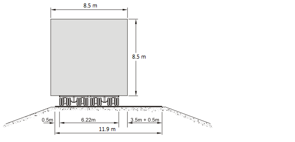
Figure 1: Full Width Sealed, Kerbed and Unkerbed Single Carriageway Roads
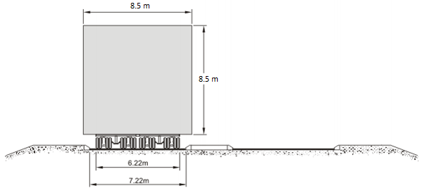
Figure 2: Full Width Sealed, Dual Carriageway Roads, Kerbed and Unkerbed Both Sides
The carriageway widths in Figures 1 and 2 have been derived to facilitate the passage of OSOM vehicles and are based on straight sections of road. At curves the required width should be determined using vehicle swept paths. The minimum seal width on straights to accommodate the nominated OSOM trailer platform is 7.22 m.
For two lane single carriageway roads consideration can be given to extending the road seal width to allow other traffic to flow in the opposite direction. The required road seal width is shown in Figure 1.
For dual carriageway roads vehicles travelling in the same direction as the OSOM vehicle will need to queue behind until there is an opportunity to overtake the OSOM vehicle through the provision of additional seal widening, or when the OSOM vehicle has moved into a holding bay.
OSOM holding bays can be installed at suitable locations where the OSOM vehicle can pull-off the road, allowing vehicles queued behind an OSOM vehicle to pass. On more heavily trafficked roads, the provision of bays alone may result in unacceptable bay spacing. In such cases, widening of the road to allow other road users to pass the slow moving OSOM vehicle may be considered. A copy of a typical holding bay drawing is attached in Appendix D.
Entry ramps and exit ramps should be treated the same way as a dual carriageway road kerbed both sides. Required sealed width is as shown in Figure 2.
In urban or "built up" areas, site specific issues such as non-removable roadside furniture vegetation etc. must be determined and planned for.
6.5 Median Central and Left Turn Islands
The requirements for the median and turning islands are based on allowance for the load overhang. In all instances, traffic islands and medians should be retained, albeit the form may vary from the current standards.
- Absolute maximum height for trafficable median/central island, with semi-mountable or mountable kerb and reinforced concrete infill shall be 150 mm.
- Where the central median/central island is non-trafficable and has obstacles or non-removable road furniture, the absolute minimum median width shall be determined by allowing 0.5 m clearance (on both directions of travel) to the obstacles or non-removable road furniture.
Note: Safety of other traffic including pedestrians and cyclists should be considered when using mountable kerbs.
6.6 Clearances
For clearance envelope requirements, refer to the “over-width routes” using the Main Roads HVS Network Map Tool.
The desirable minimum clearance envelope requirements for OSOM vehicle corridors is 10 m high by 10 m wide. As shown in Figure 3 the following OSOM vehicle clearances shall be provided
- 1.0 m - absolute maximum height of non-removable roadside furniture, relative to road surface, where load overhangs medians, islands and verges;
- 0.75 m - desirable minimum lateral clearance between laden vehicle and non-removable roadside furniture which exceeds 1.0 m height; and
- 0.5 m - absolute minimum lateral clearance between laden vehicle and traffic signal post target boards and roadside furniture.
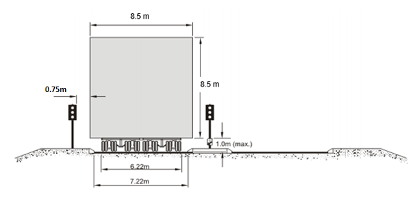
Figure 3: Clearances Envelope Requirements
6.7 Grade Separation
Where roads are to be grade separated the OSOM corridor should desirably pass over crossing roads to reduce bridge clearance requirements and costs.
Where the OSOM corridor passes under the crossing road and the crossing road links to the OSOM corridor with an interchange, a diamond shape interchange parallel to the corridor should be installed to minimise clearance requirements at the interchange. If there is no connection between the OSOM corridor and the crossroad or if there is an existing non-diamond interchange, an alternative route (a detour only for the use of OSOM vehicles or cross over to opposite carriageway) should be considered with the development of an appropriate clearance, based on suitable treatment satisfying the minimum design requirements as specified in Section 6.6 Clearances.
6.8 Grades and Superelevation
The nominated OSOM vehicles can only accommodate certain level differences over the length of the trailer. This difference is trailer specific ranging from 460 mm for the Drake 20 trailer to 500 mm for the Nicholas trailers. As the Drake 20 trailer can only accommodate a 460 mm level difference and is longer than the other trailers it is to be adopted as the basis of design.
The level difference characteristics of the OSOM trailers are to be considered were there are changes in longitudinal road gradients as shown in Figure 4, as well as level differences created by road crossfall or superelevation.
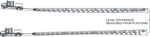
Figure 4: Level Difference Over Platform
The following grades and superelevation are recommended. These requirements should not override the other traffic engineering standards specified in Section 6.10.
Maximum grade 6%
Maximum superelevation on main carriageway 6%
For loop ramps, up to 7% maximum superelevation can be used as long as it satisfies the level difference requirement.
6.9 Other Road and Traffic Engineering Standards
The design must comply with all other Main Roads and Austroads Road Design and Traffic Engineering Standards (which will be applicable for general traffic).
6.10 Bridges and other Structures
All structures shall be designed to accommodate nominated axle loads for the high/wide loads route trailers or approved equivalent listed below:
- Drake 20 row 'Two File' at 1.80 m axle spacing and 3.70 m spread with 15 t per row;
- Drake 20 row 'Two File' at 1.80 m axle spacing and 3.70 m spread with 18 t per row, for Pilbara only;
- Nicolas 22 row 'Two File' at 1.55 m axle spacing and 2.99 m spread with 14 t per row; and
- Nicolas 16 row 'Side by Side Four File' at 1.55 m axle spacing and 6.22 m spread with 20.5 t per row.
Details of these vehicles are included in Appendix B. The steer load is 7 t and the drive is 18.5 t for each block truck required to move the trailers, as detailed in the attached diagrams. However, consideration should also be given to whether a twin steer load of 12 t and a tri-drive load of 27 t will impact the bridge and other structure requirements.
All vehicles shall be treated in the same manner as the Group 2 Vehicles, refer Bridge Branch Design Information Manual (Doc no. 3912/02-4 and 3912/02-5).6.11 Pavement and Surfacing
The OSOM vehicles can consist of platform trailers with the axle spacings and axle masses shown in Section 6.10.
All new pavements shall be designed in accordance with the Main Roads Standard Design Brief, Sections 204.3 Pavements and 204.4 Surfacings.
6.12 Other Considerations
The above represent the design criteria that should be used to maintain traffic control and road safety. It must be recognised that there may be situations where alternative methods of traffic control are necessary. The options detailed below need to be considered only as an exception to the design principles adopted above. Permanency of the route is an essential requirement.
- Where traffic signals or regulatory signs such as STOP and KEEP LEFT cannot be relocated to a permanent position clear of the laden vehicle, detachable posts may be located in sleeves cast into the traffic island to permit easy removal. Before incorporating this arrangement into the design, ongoing operational costs should be assessed against costs of other available options. These signal/signposts need to be either bolted or padlocked to the footing sleeve. Refer to Main Roads Standard Specification 601 - Signs, for a list of approved removable signpost fixing devices.
- Where OSOM vehicle turning movements are constrained at intersections median cross overs (with removable barriers) and traffic contra flow arrangements may be considered to avoid significant impact on major intersections.
- Where OSOM vehicle access is constrained in clearly identified areas, crossing over to the opposite carriageway of a dual carriageway through the median (with removable barriers) may be permitted.
To accommodate crossing over to the opposite carriageway, flush medians can be provided by using mountable or any other low profile kerb. A removable barrier such as bollards may be required along the centre of the flush median (parallel to the carriageway) to prevent U-turn movements by other vehicles. Any removable barrier should not be hazardous to other motorists.
The circumstances for the above shall be clearly identified in the development of the concept design plans for the route and necessary approvals shall be obtained from the relevant Traffic and Safety Services Manager.
7. Services
7.1 Western Power
Overhead Distribution power lines up to 33 kV crossing OSOM corridors should be relocated or placed underground.
Overhead Transmission power lines 66 kV to 330 kV crossing OSOM corridors should be relocated; or raised to provide the required clearance to move OSOM vehicles while the systems are energised. The Western Power safe approach unescorted clearance for Transmission lines are shown in Appendix E and will determine the raised height of Transmission lines or their relocation.
When determining clearances the desirable minimum clearance envelope is 10 m wide x 10 m high plus the electrical clearance requirements.
The Western Power contact details can be found in Section 1.0 Contacts.
7.2 Other Services
Any existing manholes or other service structures within the swept path of the OSOM vehicle should be checked for structural adequacy.
8. Traffic Management
8.1 General
OSOM movements have potential to impact negatively on traffic flow and the safety of other road users. It is therefore necessary to consider and plan for the management of these impacts. The overall efficiency and safe operation of the road network must be managed by balancing of:
- Availability of holding bays, seal widenings and other passing opportunities,
- Number of OSOM movements and temporal allocation (time of day/week) for OSOM movements and
- Adequate Traffic Management Plans prepared and implemented that manage impacts and minimise delays to other traffic.
However, it may not always be possible to achieve the desirable holding bay and seal widenings due to constraints such as land availability, environmental issues or limited funds.
The interaction between OSOM vehicles and other traffic will typically occur in two distinctly different situations:
- single carriageways with two-way traffic flow and
- dual carriageways where the traffic flow on any one carriage way is in one direction.
8.2 Target level of service standards for OSOM operations
The impact of OSOM vehicle movements on other road users can be measured in terms of either delay or maximum queue length (number of vehicles). Indicative Level Of Service (LOS) is as follows:
- Delay to other road users - maximum 5 minutes additional travel time (especially relevant on higher trafficked roads)
- Maximum queue length - 50 vehicles (more relevant on lower trafficked roads)
The practicality of achieving these indicative LOS targets depends on consideration of factors such as class/importance of the road, traffic volume (daily and peak hour), general traffic speed, OSOM vehicle speed, number and duration of OSOM movements and funding available for infrastructure.
8.3 Traffic management on single carriageway roads
On single carriageway roads the preferred traffic management measures include:
- the provision of sufficient / additional seal width to allow traffic travelling in the direction opposite to OSOM vehicle to pass the OSOM and
- holding bays at regular intervals to allow following traffic to pass the OSOM vehicle without experiencing excessive delay.
However, if this is not achievable it may be necessary to prohibit traffic flows in the direction opposite to the OSOM vehicle movement. If the road network allows, it may be possible to establish diversions for general traffic to alternative routes to minimise delays and disruption. However, this may not be possible for the diversion of permit vehicles using the designated OSOM route.
8.4 Traffic management on dual carriageway roads
On dual carriageway roads the preferred traffic management measures include:
- the provision of sufficient / additional seal width to allow traffic travelling in the same direction as OSOM vehicle to continuously pass the OSOM movement and / or
- holding bays at regular intervals to allow following traffic to pass the OSOM vehicle without experiencing excessive delay.
However, if this is not achievable the impact on other road users can be managed via the provision of holding bays at appropriate intervals.
9. Appendices
Appendix A
|
DETAIL MAP |
LINK |
|
Over-width routes |
Appendix B
For vehicle turning template drawings refer below:
|
TRAILER TYPE |
TURNING TEMPLATE |
TRAILER WIDTH |
|
Drake 20 Row '2-File' |
4.88 m |
|
|
Drake 20 Row '2-File' |
3.20 m |
|
|
Nicolas 22 Row '2-File' |
2.99 m |
|
|
Nicolas 16 Row '4-File' |
6.22 m |
Note that the above turning template drawings do not include load widths, these should be determined by referring to OSOM corridor maps, or as specified by the Main Roads Project Manager.
For software modelling of swept paths Main Roads provides custom modelled OSOM vehicles for Autodesk Vehicle Tracking. These modelled vehicles do not include load widths; these need to be included by the designer as an offset to the vehicle. Refer to the link below for custom modelled OSOM vehicles
Appendix C
Appendix D