Chapter 2 - Signs Pavement Marking
Table of Contents
The use of traffic signs and pavement marking shall be in accordance with the general principles set out in AS 1742.2 to AS1742.14 for the various traffic situations and traffic control devices. However, where Main Roads' practice differs from these standards, the following guidelines, pertaining to the equivalent Australian Standards section shall be adhered to:
Traffic Control Devices for General Use
The use of traffic signs and pavement marking shall be in accordance with the general principles set out in AS 1742: Parts 1 - 14 for the various traffic situations and traffic control devices.
This document does not re-write sections of the Australian Standards, but provides references to relevant sections of Standards along with approved Main Roads variations and additions to the Standards.
The following guidelines are listed and described in order of traffic control devices contained in AS 1742.2 - Part 2: Traffic Control Devices for General use.
1.1 Traffic Control Devices for General Use
1.1.1 At Intersections
1.1.1.1. General
The traffic control devices for use at intersections and sets out the principles for their installation shall be in accordance with Section 2 of AS 1742.2 (1994).
1.1.1.2. Control by Give Way and Stop Signs
Main Roads drawing 200431-0002 (Ref:1742.2 Section 4.4 - Transverse Lines) pedestrian lines - see 2.2.1.10 below and 1742.10.
1.1.1.3. Barrier lines and pavement markers at Un-Signalised Intersections
1.1.1.4. Longitudinal Lines Along Major Road at Un-signalised Intersections
(Ref:1742.2 Section 4.3.10) separation, lane, barrier, edge and edge lines @ CAH kerbed intersections.
1.1.1.5. Longitudinal Lines Along Minor Roads at Un-Signalised Intersections
1.1.1.6. Continuity Lines (4.3.6.)
Ref:1742.2 Section Drawing 9931-0198
1.1.1.7. Turn Lines (4.3.7)
Ref:1742.2 Section Drawing 9931-0198
1.1.1.8. Kerb Marking
new drawing reqd.
1.1.1.9. Hazard Boards
new drawing reqd.
1.1.1.10. Roundabout Control
Design and installation of roundabout shall be in accordance with Geometric Design of Roundabouts.
1.1.1.11. Control by Traffic Signals
1.1.1.12. Lane Drop Beyond Signalised Intersection
(AS 1742 Part 2 Section 2.7.3 with new drawings).
Fig 2.3 AS 1742 Part 2
1.1.1.13. Lane drop a cross intersection (new)
1.1.1.14. Regulation of Movements at Intersection
1.1.1.15. Intersection Warning Signs
1.1.1.16. Guide Signs
1.1.1.17. Route Markers
1.1.1.18. Pavement Markings at Intersections
1.1.1.19. Hazard Markers and Other Devices
Policy
Purpose
The purpose of this document is to detail Main Roads' policy on the regulatory signing of intersections where an unsealed carriageway intersects with a sealed carriageway.
Scope
This policy is to be applied in conjunction with the policy guidelines to provide a consistent approach to the regulatory signing of intersections of unsealed carriageways with sealed carriageways on all roads in Western Australia.
Background
The Australian Road Rules were endorsed by all State and Territory Ministers for Transport in 1999 and the majority of those rules were included in Western Australia's Road Traffic Code 2000. Prior to the rules being adopted, the Road Traffic Code 1975 (Regulation 610) required all vehicular traffic on unsealed carriageways to give right-of-way to vehicular traffic on sealed carriageways. This regulation was a means of providing safety at these intersections and obviating the need for regulatory GIVE WAY signs. This regulation was not agreed Nationally, as is necessary, and consequently it was not included in the new Road Traffic Code 2000.
It is therefore necessary, for reasons of safety, that these intersections be reviewed to determine whether regulatory GIVE WAY (or STOP) signs are required.
This Policy and Guidelines is to ensure regulatory signing of these types of intersections is consistently applied.
Definitions
| Carriageway | A portion of a road that is improved, designed or ordinarily used for vehicular traffic, and includes the shoulders, and areas, including embayments, at the side or centre of a carriageway, used for stopping or parking of vehicles; and, where a road has 2 or more of those portions divided by a median strip, the expression means each of those portions, separately. |
| Intersection | a. The area where two or more carriageways meet; or b. The area within which vehicles, travelling by, on or from different carriageways may come into conflict. |
| Road Traffic Code 2000 | Regulations under the provisions of the Road Traffic Act. |
| Road | Any highway, road or street open to, or used by, the public and includes every carriageway, footway, reservation, median strip or traffic island thereon.> |
| T intersection | An intersection where two carriageways meet, (whether or not at right angles), and one of the carriageways ends. |
Policy Guidelines
These guidelines are to be applied at locations where an unsealed carriageway and a sealed carriageway meet.
Common Intersection Layouts
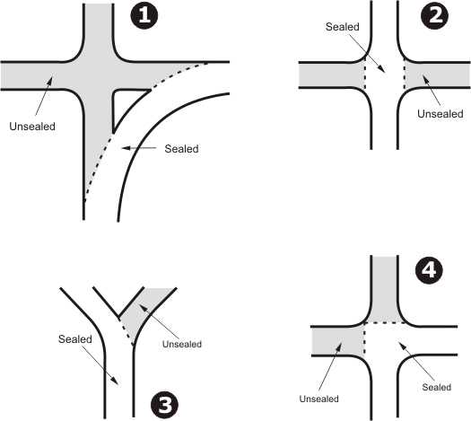
The layouts of intersections vary considerably. In consultation with Regional Managers the following diagrams are considered to represent the majority of sealed/unsealed carriageway intersections that exist in Western Australia.
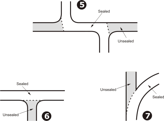
Of these layouts those numbered 1, 3, 5, 6 and 7 are classified as T intersections under Road Traffic Code regulations. However, apart from intersections of the type shown as layout 6, special treatments are necessary to ensure they conform to the T intersection definition and regulations that apply. Those treatments include regulatory signs, warning signs and, in some cases road markings. Intersection types 2 and 4 are those, where in the absence of regulatory signs, normal give-way-to-the-right rules would apply.
The treatments necessary for all layout types are addressed in these policy guidelines.
Intersection Treatments
The treatments recommended in the following are the minimum that should be applied as a consequence of the absence of the previous regulation which required traffic on unsealed carriageways to give way to traffic on sealed carriageways. Intersections that are assessed as hazardous for other reasons should be treated as necessary using accepted traffic management practices including the application of signing standards according to AS 1742. This includes the need for warning signs on any of the approaches, or hazard markers, etc.
Treatment of Intersection Types 1 and 7
A GIVE WAY sign shall be installed on unsealed road approaches of Intersection Types 1 and 7. In addition, a GIVE WAY line shall be installed where there is sufficient sealed area available. At least two metres of sealed pavement from the intersection along the unsealed road approach is necessary for a GIVE WAY line to be installed. Where the sealed road is at least 5.5 m wide, a separation line should be applied through the curve and an edge line marked on the outside of the curve.
Treatment of Intersection Type 2
A GIVE WAY sign shall be installed on both unsealed road approaches of Intersection Type 2. However, if application of sight distance criteria for normal intersections signing requires STOP signs to be installed, then they shall be installed on both unsealed road approaches. If at least two metres of sealed pavement from the intersection along the unsealed approach is available to install GIVE WAY LINES or STOP lines as appropriate, then these shall also be provided.
Treatment of Intersection Type 3
A GIVE WAY sign may be required to be installed on the unsealed road approach of Intersection Type 3, depending on whether it is sufficiently obvious that the unsealed road is the terminating road or not. If any doubt exists then a GIVE WAY sign is required to be installed. A GIVE WAY line is only required where two metres of sealed pavement is available to install the line. In addition, where the sealed road is at least 5.5 m wide and centre lining does not already exist, a separation line should be applied through the curve.
Treatment of Intersection Types 4
Unsealed carriageways may be an indication of low vehicle usage and, if this is so, it is acceptable and appropriate that regulatory signs be placed on the unsealed road approaches of Intersection Type 4. Regulations require traffic travelling on the unsealed road approaching a STOP sign or GIVE WAY sign to give way to all vehicular traffic. This includes traffic travelling on the intersecting carriageway as well as traffic turning right in front of vehicles on the STOP sign or GIVE WAY sign controlled approach. Whether GIVE WAY or STOP signs are appropriate is a matter of assessment of sight distance (in accordance with existing criteria). GIVE WAY lines or STOP lines as appropriate need only be installed where at least two metres of sealed pavement is available.
Treatment of Intersection Type 5
GIVE WAY signs shall be installed on the unsealed road approaches of Intersection Type 5. GIVE WAY lines shall only be installed where at least two metres of sealed pavement approaching the intersection is available.
Treatment of Intersection Type 6
In respect to Intersection Type 6, normal give-way requirements apply and therefore no signs or special line marking is required. However, GIVE WAY or STOP signs with appropriate lining may be installed where necessary to conform with other criteria.
Approval
Approval from the Commissioner of Main Roads, or authorised delegate, shall be obtained prior to installing GIVE WAY signs or STOP signs in accordance with these Policy and Guidelines.
Application of Policy and Guidelines
The policy and guidelines apply to intersections of sealed and unsealed carriageways.
References
AS 1742 Manual of Uniform Traffic Control Devices
Road Traffic Code 2000
Road Traffic Act 1974
1.1.2 Between Intersections
1.1.2.1. General
Generally, the devices should be used for control of traffic between intersections and sets out the principles for their installation shall be in accordance with Section 3 of AS 1742.2 (1994).
1.1.2.2. Guide Posts and Delineators
Guide Posts and Delineators shall be designed and installed in accordance with Guide to the Design of Guide Posts.
1.1.2.3. Pavement Bars
Main Roads does not use pavement bars.
1.1.2.4. Treatment of Substandard Horizontal Curves
(3.5) Ref:1742.2 Section
1.1.2.5. Treatment of sub-Standard Vertical Curves/Humps
(3.5) Ref:1742.2 Section
1.1.2.6. Treatment of Approaches to Structures and Obstructions
(3.6) Ref 1742:2 Section.
1.1.2.7. Changes in Pavement Width
(3.7)Ref:1742.2 Section.
1.1.2.8. Climbing and Overtaking Lanes, and Turnouts
(3.8) Ref:1742.2 Section.
1.1.2.9. Steep Grades and Safety Ramps
(3.9) Ref 1742.2 Section
1.1.2.10. Water Crossings
(3.10) Ref 1742.2 Section.
1.1.2.11. Physical Obstructions and Hazards
(3.11) Ref 1742.2 Section
1.1.2.12. Geographical Feature Signs (G6)
(3.12) Ref:1742.2 Section
1.1.2.13. Kilometre Posts
(3.13) Ref: 1742.2 Section
1.1.2.14. Variable Use Lanes Signs
(3.14) Ref: 1742.2 Section
1.1.2.15. Miscellaneous Signs.
1.1.3 Design Standards
General
Pavement markings includes the lines, symbols, letters, numerals and raised pavement markers used on road pavements or kerbs for the purpose of guiding the road user. Pavement markings are an important component of any intersection design and should be used accordingly, to enable the most efficient use of a particular intersection treatment.
Traffic signs are used to carry information to the road user. The signs may carry instructions which the road user is required to obey, warning of hazards or information about routes, destinations or points of interest. The number of signs should be restricted to the minimum, consistent with their particular requirements, as signs tend to lose their effectiveness with overuse.
Some design requirements, which have been adopted by Main Roads and included in these standards, may vary from or are additional to the guidelines in the AUSTROADS 'Guide to Traffic Engineering Practice' and the Standards Australia Manual of Uniform Traffic Devices AS 1742.
Removal of Markings
Pavement markings shall be removed or obliterated where the road conditions or restrictions cause the markings to become redundant by the design of the intersection or traffic control signals.
Pavement marking shall be obliterated or removed where necessary, with 5-7 mm aggregate seal or by grinding off, depending on the existing surface.
Where pavement marking is to be removed, the details should be indicated on the drawings as part of the design.
Removal/Addition of Signs
Signs shall be installed, relocated or removed where the design of the intersection or traffic control signals alter the road conditions or restrictions, causing the signing requirements or placement to change.
Where any changes are made to signing requirements these shall be indicated on the drawing with the words 'INSTALL', 'RELOCATE" or REMOVE" above the particular sign.
Colour of Pavement Marking
The colour of pavement marking shall be white except for the alternative uses of yellow specified as follows:
- Exclusive bus lane,
- Bus embayment,
- Taxi stand and Loading Zone,
- Rail crossing approaches.
- Specific marking as required.
Where yellow pavement marking is intended to be used to mark these facilities, it must be indicated on the drawing.
Transverse Lines
Stop Lines
The minimum width of stop lines shall be:
- 300 mm - unsignalised intersections (includes unsignalised sliproads),
- 450 mm - signalised intersections and railway crossings,
- 600 mm - specified locations or approach speed >80 km/h.
Stop lines at intersections and mid block pedestrian locations should be located:
- to minimise inter-green and clearance times,
- at least 1.0 m clear of swept path of vehicles turning from other intersection approaches,
- the dual primary signal post,
- at an angle between 70 and 110 degrees to the direction of travel,
- generally parallel to the through alignment of the intersecting road,
- 1.0 to 1.5 m from pedestrian ramps, gaps and crossing lines at signalised intersections,
- 1.5 to 2.0 m from pedestrian ramps, gaps and crossing lines but not less than 10.0 m in advance of the secondary signal post at pelican traffic control signals.
Stop lines are generally not used on slip roads except where sight restrictions or other particular situations may require a stop line to be installed in preference to a holding line.
Give Way and Holding Lines
The dimensions of Give Way and holding lines are 300 mm wide with 600 mm line segments and 600 mm gaps.
Give Way and holding lines are set back at least 600 mm from the kerbline projection of the intersecting road.
Give Way lines are generally used on unsignalised slip roads associated with signalised intersections.
Where heavy haulage aprons occur as part of the intersection, the holding line shall not be marked on the apron.
Pedestrian Crossing Lines
The dimensions of pedestrian crossing lines are 80 mm wide with 600 mm line segments and 600 mm gaps.
Pedestrian crossings should be located:
- 2.0 m - minimum pedestrian path width between lines at most traffic control signal locations,
- 5.0 to 6.0 m minimum distance between lines at pelican traffic control signal locations,
- as near as possible to the desire lines of pedestrians,
- as near as possible to the shortest path across the intersection,
- but as close as possible to parallel vehicle movements,
- where slip roads and corner islands are installed,
- the lines must connect from the median to the corner island,
- in conjunction with pedestrian walk signal aspects.
Longitudinal Lines
Separation Lines
Separation lines are used to separate opposing vehicle movements.
Separation lines are 80 mm wide and the dimensions for broken separation lines are 3.0 m line segments with 9.0 m gaps.
Double Barrier Lines
The double barrier line is used to prohibit vehicles using the opposing traffic lanes.
Double barrier lines consist of two parallel lines each 80mm wide with 80mm between the lines.
On the approach to an intersection, the double barrier line shall start at least 12.0 m, (preferably 25.0 m) from the tail of the island but the road width between the double barrier line and the kerb cannot be less than 5.5 m or 6.0 m where 3.0 m lanes are to be provided.
In the event that the edge of road is unkerbed and has 1.0 m sealed shoulder, the width between the double barrier line and edgeline can be 4.5 m.
Some locations may require a 'no overtaking' tail prior to the double barrier lines.
The double barrier line terminates at the closest point to the intersection as follows:
- on the left side of the island,
- adjacent to the KEEP LEFT sign for narrow central islands,
- 0.6 m from the kerb, but on the road alignment, for short medians with a protected right turn lane.
Lane Lines
Lane lines are used for vehicles moving in the same direction (i.e. in a through direction or in the same turning direction).
Lane lines are 80 mm wide and the dimensions for broken lane lines are 3.0 m line segments with 9.0 m gaps.
The length of the unbroken barrier line between lanes on traffic control signal approaches should normally be 25.0 m from the stop line. The length of the line may be extended or shortened (e.g. for driveways) where necessary and the safety of the road user is not compromised.
The broken lane lines start at 9.0 m from the unbroken lane line on the approach to an intersection and from the median traffic signal post on the departure side of the intersection. The broken lines should not extend beyond the end of the double barrier line at the farthest point from the intersecting roads or where the lane width will be less than 3.0 m.
All line segments for broken lane lines should be kept parallel longitudinally.
Continuity Lines
Continuity lines are used to indicate the edge of the portion of the road assigned to through traffic and where it is intended the broken line may be crossed by traffic turning at the intersection or entering/leaving an auxiliary lane.
Continuity lines are 150mm wide on freeways, bus and taxi lanes and bus bays and 120mm wide for normal usage. The dimensions for broken lane lines are 1.0m line segments with 3.0m gaps.
The length of the unbroken continuity line between through and turning lanes on traffic control signal approaches should normally be 25.0m from the stop line. The length of the line may be extended or shortened (e.g. for driveways) where necessary and the safety of the road user is not compromised.
The broken lane lines start at 3.0m from the unbroken lane line on the approach to an intersection.
Where a bus embayment occurs a yellow broken continuity line shall be used.
Cycle lanes shall be distinguished from other traffic lanes by the use of continuity lines.
All line segments for continuity lines should be kept parallel longitudinally.
Edge Lines
Edge lines delineate the edge of the travelled way and are used to demarcate islands, shoulders and cycle lanes.
Where heavy haulage aprons occur the edgeline shall be marked, on the road surface adjacent to the low profile kerb, from the approach to the apron to the holding line.
Median Road markings
Median road markings consist of longitudinal outline markings (edge lines) and diagonal markings. For outline markings, refer to Drawing No. 9931-0198. For diagonal markings, refer to Drawing No. 200331-091.
The median terminates at the closest point to the intersection as follows:
- on the both sides of the island,
- 4.5 m for narrow central islands,
- 0.6 m from the kerb, but on the road alignment, on the approach side for short medians with a protected right turn lane,
- adjacent to the island on the departure side of a median.
Other Marking
Turn lines
Turn lines are used on major or complex intersections to guide the proper course, as determined by the swept path, to be followed by turning traffic.
The dimensions for turn lines are 75 mm wide with 600 mm line segments and 600 mm gaps.
Turn lines are used at intersections with multiple turns in the same direction and all diamond traffic control signal locations.
At diamond turning movement locations, a full line is also marked at the closest points of the opposing turns, as determined by the swept path of the appropriate vehicle. The minimum width between opposing turns is 2.0 m. The full diamond line is 150 mm wide and the length is normally 5.0 m, the line should preferably be confined within the median alignment.
Arrows
Intersection arrows are necessary to ensure correct lane usage.
The choice and need for pavement arrows shall be determined and based on the requirements as set down in Australian Standard 1742.14 - Figure 6.1.
For turning lanes, three arrows should be placed in that lane. The farthest arrow from the intersection in a turning lane should be placed where the lane is first fully developed.
For through lanes only two arrows should be placed in that lane.
The 20.0 m from tail to head spacing between arrows may be adjusted to no less than 15.0 m or no greater than 30.0 m to enable provision of sufficient arrows.
Where arrows are placed in adjacent lanes, the arrows shall be adjacent to turn arrows. Arrows should be kept parallel longitudinally.
Where a through lane becomes an exclusive turning lane (eg open ended lane where turn lanes are not developed in the median), signs of the type LEFT (RIGHT) LANE MUST TURN LEFT (RIGHT) shall be installed to supplement the pavement arrows. Additional turn arrows may be installed for advance warning to motorists.
U-turns are prohibited at traffic control signals in Western Australia, but isolated locations have U-turn breaks in the median at greater than 30.0 m from the intersection.
Pavement Messages and Symbols
The use of pavement messages should be minimised, as these may be hazardous if placed in the path of braking vehicles.
Generally only BUS/TAXI LANE and KEEP CLEAR messages are used in specified locations.
Rail crossing pavement marking is used at railway level crossings used by passenger trains.
Raised Pavement Markers
Retro-reflective raised pavement markers are used in conjunction with pavement lining at all signalised intersections.
The two colours used in Western Australia are white and yellow. The general applications of raised pavement markers including colour, spacing and pattern are indicated in Drawing 9120-0158.
Gore Marking
The edge lines of the gore marking are 150 mm with 500 mm wide marked chevrons and 4.0 m gaps. The chevrons are 150 mm from the edge lines and are internally angled at 90o
Gore marking is used on the approaches to corner islands
Signs
Regulatory Signs
Keep Left (R2-3A) - KEEP LEFT signs shall be installed on approaches to central islands and short medians in conjunction with double barrier lines. The signs shall be 4.5 m from the tail of the island.
Where a central island or median is preceded by a marked median a KEEP LEFT sign is not required.
No Left (Right) Turn (R2-6A) and No Entry (R2-4A) - These signs must be consistent with the pavement marking and the traffic control signal displays. A minimum of two signs shall be displayed for each direction of travel and attached to the signal posts that would have been used, had signal aspects controlling the banned turn been installed.
In the event that it is necessary to prohibit certain movements in peak periods only, illuminated signs shall be installed as a component of the traffic control signals.
Left (Right) Lane Must Turn Left (Right) (R2-9A) - Where a through lane becomes an exclusive turning lane at the intersection (e.g. open ended lane where turn lanes are not developed in the median) these signs shall be installed to supplement the pavement arrows.
A minimum of two signs shall be displayed for each direction of travel with one sign attached to the primary signal post (for LEFT TURN MUST TURN LEFT) or the dual primary signal post (for RIGHT TURN MUST TURN RIGHT) and the other sign should be as near as practicable to the start of the turn lane.
Parking (R5-35A) - Signs controlling and prohibiting parking are used extensively in the vicinity of signalised intersections.
To improve the intersection capacity and to reinforce the Road Traffic Code of Western Australia, certain legal requirements and design implications must be observed.
The general minimum length of No Standing shall apply as follows:
- 6.0 m - from a property line,
- 9.0 m - from a traffic island,
- 35.0 m - from the Stop line on the approach to traffic signal,
- 18.0 m - to the approach side of a bus stop,
- 9.0 m - on the departure side of a bus stop,
- within the length of a turn lane (including tapers),
- within the length of a bus bay (including tapers),
- within 3.0 m of a double line.
Warning Signs
Signals Ahead Symbolic Sign (W3-3B) - This sign is normally installed about 120 m from the intersection on all approaches to a signalised intersection. Street name tags (MR-GS-3 or 4) attached to the sign identify the particular road being approached.
Advance Warning Flashing Signal Sign (MR-WAW-1) - For specific locations the Advance Warning Flashing Signal signs are installed in place of the Signals Ahead Symbolic Sign. Street name tags (MR-GS-7 or 8) are attached to the sign identify the particular road being approached.
1.1.4 Design Procedures and Presentation
GeneralThe pavement marking and minor signing drawing is produced in conjunction with the intersection and traffic control signal designs.
The intersection and traffic control signal design plans should be used as a background layout for all pavement marking and signing design plans.
Where minor works are proposed, existing plans may be utilised to produce a pavement marking and signing drawing that meets the design requirements.
This chapter is to be read in conjunction with Road and Traffic Engineering Guidelines - Design Presentation
Drawings
All drawings should be prepared to microfilm standards on standard size sheets and be numbered in accordance with the Main Roads Drawing Numbering System. One or more blocks of drawing numbers will be made available as required. Drawings should include the standard Main Roads borders and title blocks and are to be produced on a CAD system. Main Roads will provide software in DXF or DWG format to generate borders and title blocks, which may be adaptable to the Contractor's CAD system.
Final drawings are to be plotted onto film or paper that is acceptable to Main Roads.
Where pavement marking and signing drawings are required in conjunction with a new or modified traffic control signal location, the background should include:
- Final layout of kerbing, traffic islands and driveways,
- Property boundaries,
- Footpaths,
- Traffic signal posts,
- Detector Loops,
- Existing pavement marking,
- Existing signing location and symbolic sign. (with AS or Main Roads code number).
After the completion of any works at a traffic control signal location, an As Constructed Drawing shall be prepared or the existing As Constructed shall be updated to reflect the works or modifications that have been carried out.
The set of drawings prepared for pavement marking and signing design should generally include the following:
Pavement Marking and Minor Signing Plan
(Scale - 1:500)
To include:
- Proposed intersection layout
- Traffic signal posts,
- Detector loops,
- Transverse lines - Stop lines,
- Give Way lines,
- Pedestrian crossing lines,
- Longitudinal lines - Separation and barrier lines,
- Lane lines,
- Edge lines,
- Turn guide lines,
- Pavement arrows,
- Regulatory signs,
- Warning signs
As Constructed Pavement Marking Signing Drawing
(Scale - 1:500)
To include:
- Proposed intersection layout
- Traffic signal posts,
- Detector loops,
- Transverse lines - Stop lines,
- Give Way lines,
- Pedestrian crossing lines
- Longitudinal lines - Separation and barrier lines,
- Lane lines,
- Edge lines,
- Turn guide lines,
- Pavement arrows,
- Regulatory signs,
- Warning signs
All pavement marking and signing design and as constructed drawing shall be longitudinally dimensioned starting from the nose of the central island. These dimensions shall be to the nearest metre. Clearances and widths of lanes and turning guide lines shall be dimensioned to the nearest 0.1 metre.
At the completion of the project, all completed drawings should be forwarded to Main Roads as original transparencies and on computer disk in DXF or DWG format. These disks and all drawings are deemed to be the property of Main Roads.
Specifications
Specifications shall be prepared in conjunction with the traffic control signal project and should include details not covered by the drawings and any further detail required to carry out the works.
The specifications should include the following, but not limited to:
- Materials selected,
- Installation standards and practices,
- Work required,
- Work to be carried out by others.
Approval of Drawings
Prior to submission to the Superintendent, the final drawings shall be signed as 'Approved' to signify all aspects of the pavement marking and design are in accordance with standards and practices of Main Roads, AUSTROADS and Australian Standards and that an independent check has been carried out.
1.1.5 Applicable Drawings
For current pavement marking drawings for general use, (refer to the Pavement Marking Section under the Standard and Contract Drawings).
For current pavement marking drawings related to Local Area Traffic Management Devices, refer to the Local Area Traffic Management - Signs and Pavement Marking Section under the Guideline Drawings).
|
Appendix 1 - Approved Road Marking Materials
|
||||||||||||||||||||||||||||||||||||||||||||||||||||||||||||||||||||||||||||||||||||||||||||||||||||||||||||||||||||||||||||||||||||||||||||||||||||||||||||||||||||||||||||||||||||||||||||||||||||||||||||||||||||||||||||||||||||||||||||||||||||||||||||||||||||||||||||||||||||
Traffic Signals
The use of traffic signs and pavement marking shall be in accordance with the general principles set out in AS 1742: Parts 1 - 14 for the various traffic situations and traffic control devices.
This document does not re-write sections of the Australian Standards, but provides references to relevant sections of Standards along with approved Main Roads variations and additions to the Standards.
The following guidelines are listed and described in order of traffic control devices contained in AS 1742.14 - Part 14: Traffic Signals.
1.1.1 Purpose
The purpose of this manual is to detail the standards in the design of pavement marking and minor signing where traffic control signals are used to control traffic and to provide guidelines in the application of those standards.The guidelines in this document have been developed for use by Main Roads complementary to AUSTROADS Guide to Traffic Engineering Practice - Traffic Devices Part 8 and Australian Standard Manual of Uniform Traffic Control Devices. This guide should be used in conjunction with those standards.
1.1.2 Scope
The purpose of these standards is to facilitate consistent design for pavement marking and minor signing associated with traffic control signals within Western Australia.This document outlines the relevant standards and procedures to be followed when producing a pavement marking and minor signing design.
1.1.3 References
Road and Traffic Engineering Guidelines - Traffic Management Guidelines for Traffic SignalsAUSTROADS Guide to Traffic Engineering Practice - Part 7 Traffic Signals
AUSTROADS Guide to Traffic Engineering Practice - Part 8 Traffic Control Devices
AUSTROADS Design Vehicles and Turning Path Templates
STANDARDS AUSTRALIA Manual of Uniform Traffic Control Devices Parts 1 - 14 (AS 1742)
Main Roads Road & Traffic Design - Technical Standards Intersections for Traffic Control Signals 3100/05-13
Main Roads Road & Traffic Design - Technical Standards Main Roads Index of Signs Manual 3100/05/10-2
Main Roads Road & Traffic Design - Technical Standards Sign Post Design Manual 3100/05/10-6
Main Roads Traffic Design - Design Guidelines for Channelisation, Pavement Marking and Regulatory Signing 2000/001
1.1.4 Design Standards
GeneralPavement markings includes the lines, symbols, letters, numerals and raised pavement markers used on road pavements or kerbs for the purpose of guiding the road user. Pavement markings are an important component of any intersection design and should be used accordingly, to enable the most efficient use of a particular intersection treatment.
Traffic signs are used to carry information to the road user. The signs may carry instructions which the road user is required to obey, warning of hazards or information about routes, destinations or points of interest. The number of signs should be restricted to the minimum, consistent with their particular requirements, as signs tend to lose their effectiveness with overuse.
Some design requirements, which have been adopted by Main Roads and included in these standards, may vary from or are additional to the guidelines in the AUSTROADS 'Guide to Traffic Engineering Practice' and the Standards Australia Manual of Uniform Traffic Devices AS1742.
Removal of Markings
Pavement markings shall be removed or obliterated where the road conditions or restrictions cause the markings to become redundant by the design of the intersection or traffic control signals.
Pavement marking shall be obliterated or removed where necessary, with 5-7 mm aggregate seal or by grinding off, depending on the existing surface.
Where pavement marking is to be removed, the details should be indicated on the drawings as part of the design.
Removal/Addition of Signs
Signs shall be installed, relocated or removed where the design of the intersection or traffic control signals alter the road conditions or restrictions, causing the signing requirements or placement to change.
Where any changes are made to signing requirements these shall be indicated on the drawing with the words 'INSTALL', 'RELOCATE" or REMOVE" above the particular sign.
Colour of Pavement Marking
The colour of pavement marking shall be white except for the alternative uses of yellow specified as follows:
- Exclusive bus lane,
- Bus embayment,
- Taxi stand and Loading Zone,
- Rail crossing approaches.
- Specific marking as required.
Where yellow pavement marking is intended to be used to mark these facilities, it must be indicated on the drawing.
Transverse Lines
Stop Lines
The minimum width of stop lines shall be:
- 300 mm - unsignalised intersections (includes unsignalised sliproads),
- 450 mm - signalised intersections and railway crossings,
- 600 mm - specified locations or approach speed >80 km/h.
Stop lines at intersections and mid block pedestrian locations should be located:
- to minimise inter-green and clearance times,
- at least 1.0 m clear of swept path of vehicles turning from other intersection approaches,
- at the dual primary signal post,
- at an angle between 70 and 110 degrees to the direction of travel,
- generally parallel to the through alignment of the intersecting road,
- 1.0 to 1.5m from pedestrian ramps, gaps and crossing lines at signalised intersections,
- 1.5 to 2.0m from pedestrian ramps, gaps and crossing lines but not less than 10.0 m in advance of the secondary signal post at pelican traffic control signals.
Stop lines are generally not used on slip roads except where sight restrictions or other particular situations may require a stop line to be installed in preference to a holding line.
Give Way and Holding Lines
The dimensions of Give Way and holding lines are 300mm wide with 600mm line segments and 600mm gaps.
Give Way and holding lines are set back at least 600mm from the kerbline projection of the intersecting road.
Give Way lines are generally used on unsignalised slip roads associated with signalised intersections.
Where heavy haulage aprons occur as part of the intersection, the holding line shall not be marked on the apron.
Pedestrian Crossing Lines
The dimensions of pedestrian crossing lines are 150mm wide with 900mm line segments and 300mm gaps.
Pedestrian crossings should be located:
- 2.0m - minimum pedestrian path width between lines at most traffic control signal locations,
- 5.0 to 6.0m minimum distance between lines at pelican traffic control signal locations,
- as near as possible to the desire lines of pedestrians,
- as near as possible to the shortest path across the intersection, but as close as possible to parallel vehicle movements,
- where slip roads and corner islands are installed, the lines must connect from the median to the corner island,
- in conjunction with pedestrian walk signal aspects.
Longitudinal Lines
Separation Lines
Separation lines are used to separate opposing vehicle movements.
Separation lines are 80mm wide and the dimensions for broken separation lines are 3.0m line segments with 9.0m gaps.
Double Barrier Lines
The double barrier line is used to prohibit vehicles using the opposing traffic lanes.
Double barrier lines consist of two parallel lines each 80mm wide with 80mm between the lines.
On the approach to an intersection, the double barrier line shall start at least 12.0m, (preferably 25.0m) from the tail of the island but the road width between the double barrier line and the kerb cannot be less than 5.5m or 6.0m where 3.0m lanes are to be provided.
In the event that the edge of road is unkerbed and has 1.0m sealed shoulder, the width between the double barrier line and edgeline can be 4.5m.
Some locations may require a 'no overtaking' tail prior to the double barrier lines.
The double barrier line terminates at the closest point to the intersection as follows:
- on the left side of the island,
- adjacent to the KEEP LEFT sign for narrow central islands,
- 0.6m from the kerb, but on the road alignment, for short medians with a protected right turn lane.
Lane Lines
Lane lines are used for vehicles moving in the same direction (i.e. in a through direction or in the same turning direction).
Lane lines are 80mm wide and the dimensions for broken lane lines are 3.0m line segments with 9.0m gaps.
The length of the unbroken barrier line between lanes on traffic control signal approaches should normally be 25.0m from the stop line. The length of the line may be extended or shortened (e.g. for driveways) where necessary and the safety of the road user is not compromised.
The broken lane lines start at 9.0metres from the unbroken lane line on the approach to an intersection and from the median traffic signal post on the departure side of the intersection. The broken lines should not extend beyond the end of the double barrier line at the farthest point from the intersecting roads or where the lane width will be less than 3.0m.
All line segments for broken lane lines should be kept parallel longitudinally.
Continuity Lines
Continuity lines are used to indicate the edge of the portion of the road assigned to through traffic and where it is intended the broken line may be crossed by traffic turning at the intersection or entering/leaving an auxiliary lane.
Continuity lines are 120mm wide and the dimensions for broken lane lines are 1.0m line segments with 3.0m gaps.
The length of the unbroken continuity line between through and turning lanes on traffic control signal approaches should normally be 25.0m from the stop line. The length of the line may be extended or shortened (e.g. for driveways) where necessary and the safety of the road user is not compromised.
The broken lane lines start at 3.0m from the unbroken lane line on the approach to an intersection.
Where a bus embayment occurs a yellow broken continuity line shall be used.
Cycle lanes shall be distinguished from other traffic lanes by the use of continuity lines.
All line segments for continuity lines should be kept parallel longitudinally.
Edge Lines
Edge lines delineate the edge of the travelled way and are used to demarcate islands, shoulders and cycle lanes.
Where heavy haulage aprons occur the edgeline shall be marked, on the road surface adjacent to the low profile kerb, from the approach to the apron to the holding line.
Median Road marking
The edge lines of the median are 120mm with 500mm wide chevron bar markings and 10.0m gaps. The chevron bars are 120mm from the edge lines and angled at 45o to the edge lines.
The median terminates at the closest point to the intersection as follows:
- on the both sides of the island,
- 4.5m for narrow central islands,
- 0.6m from the kerb, but on the road alignment, on the approach side for short medians with a protected right turn lane,
- adjacent to the island on the departure side of a median.
Other Marking
Turn lines
Turn lines are used on major or complex intersections to guide the proper course, as determined by the swept path, to be followed by turning traffic.
The dimensions for turn lines are 80mm wide with 600mm line segments and 600mm gaps.
Turn lines are used at intersections with multiple turns in the same direction and all diamond traffic control signal locations.
At diamond turning movement locations, a full line is also marked at the closest points of the opposing turns, as determined by the swept path of the appropriate vehicle. The minimum width between opposing turns is 2.0m. The full diamond line is 120mm wide and the length is normally 5.0m, the line should preferably be confined within the median alignment.
Arrows
Intersection arrows are necessary to ensure correct lane usage.
The choice and need for pavement arrows shall be determined and based on the requirements as set down in Australian Standard 1742.14 - Figure 6.1.
For turning lanes, three arrows should be placed in that lane. The farthest arrow from the intersection in a turning lane should be placed where the lane is first fully developed.
For through lanes only two arrows should be placed in that lane.
The 20.0m from tail to head spacing between arrows may be adjusted to no less than 15.0m or no greater than 30.0m to enable provision of sufficient arrows.
Where arrows are placed in adjacent lanes, the arrows shall be adjacent to turn arrows. Arrows should be kept parallel longitudinally.
Where a through lane becomes an exclusive turning lane (eg open ended lane where turn lanes are not developed in the median), signs of the type LEFT (RIGHT) LANE MUST TURN LEFT (RIGHT) shall be installed to supplement the pavement arrows. Additional turn arrows may be installed for advance warning to motorists.
U-turns are prohibited at traffic control signals in Western Australia, but isolated locations have U-turn breaks in the median at greater than 30.0m from the intersection.
Pavement Messages and Symbols
The use of pavement messages should be minimised, as these may be hazardous if placed in the path of braking vehicles.
Generally only BUS/TAXI LANE and KEEP CLEAR messages are used in specified locations.
Rail crossing pavement marking is used at railway level crossings used by passenger trains.
Raised Pavement Markers
Retro-reflective raised pavement markers are used in conjunction with pavement lining at all signalised intersections.
The two colours used in Western Australia are white and yellow. The general applications of raised pavement markers including colour, spacing and pattern are indicated in Drawings 9120-0158 and 9120-0159.
Gore Marking
The edge lines of the gore marking are 120mm with 500mm wide marked chevrons and 4.0m gaps. The chevrons are 120mm from the edge lines and are internally angled at 90o.
Gore marking is used on the approaches to corner islands
Signs
Regulatory Signs
Keep Left (R2-3A)
KEEP LEFT signs shall be installed on approaches to central islands and short medians in conjunction with double barrier lines. The signs shall be 4.5m from the tail of the island.
Where a central island or median is preceded by a marked median a KEEP LEFT sign is not required.
No Left (Right) Turn (R2-6A) and No Entry (R2-4A)
These signs must be consistent with the pavement marking and the traffic control signal displays. A minimum of two signs shall be displayed for each direction of travel and attached to the signal posts that would have been used, had signal aspects controlling the banned turn been installed.
In the event that it is necessary to prohibit certain movements in peak periods only, illuminated signs shall be installed as a component of the traffic control signals.
Left (Right) Lane Must Turn Left (Right) (R2-9A)
Where a through lane becomes an exclusive turning lane at the intersection (e.g. open ended lane where turn lanes are not developed in the median) these signs shall be installed to supplement the pavement arrows.
A minimum of two signs shall be displayed for each direction of travel with one sign attached to the primary signal post (for LEFT TURN MUST TURN LEFT) or the dual primary signal post (for RIGHT TURN MUST TURN RIGHT) and the other sign should be as near as practicable to the start of the turn lane.
Parking (R5-35A)
Signs controlling and prohibiting parking are used extensively in the vicinity of signalised intersections.
To improve the intersection capacity and to reinforce the Road Traffic Code of Western Australia, certain legal requirements and design implications must be observed.
The general minimum length of No Standing shall apply as follows:
- 6.0m - from a property line,
- 9.0m - from a traffic island,
- 35.0m - from the Stop line on the approach to traffic signal,
- 18.0m - to the approach side of a bus stop,
- 9.0m - on the departure side of a bus stop,
- within the length of a turn lane (including tapers),
- within the length of a bus bay (including tapers),
- within 3.0m of a double line.
Warning Signs
Signals Ahead Symbolic Sign (W3-3B)
This sign is normally installed about 120m from the intersection on all approaches to a signalised intersection. Street name tags (MR-GS-3 or 4) attached to the sign identify the particular road being approached.
Advance Warning Flashing Signal Sign (MR-WAW-1)
For specific locations the Advance Warning Flashing Signal signs are installed in place of the Signals Ahead Symbolic Sign. Street name tags (MR-GS-7 or 8) are attached to the sign identify the particular road being approached.
1.1.5 Design Procedures and Presentation
GeneralThe pavement marking and minor signing drawing is produced in conjunction with the intersection and traffic control signal designs.
The intersection and traffic control signal design plans should be used as a background layout for all pavement marking and signing design plans.
Where minor works are proposed, existing plans may be utilised to produce a pavement marking and signing drawing that meets the design requirements.
This chapter is to be read in conjunction with Road and Traffic Engineering Guidelines - Design Presentation
Drawings
All drawings should be prepared to microfilm standards on standard size sheets and be numbered in accordance with the Main Roads Drawing Numbering System. One or more blocks of drawing numbers will be made available as required. Drawings should include the standard Main Roads borders and title blocks and are to be produced on a CAD system. Main Roads will provide software in DXF or DWG format to generate borders and title blocks, which may be adaptable to the Contractor's CAD system.
Final drawings are to be plotted onto film or paper that is acceptable to Main Roads.
Where pavement marking and signing drawings are required in conjunction with a new or modified traffic control signal location, the background should include:
- Final layout of kerbing, traffic islands and driveways,
- Property boundaries,
- Footpaths,
- Traffic signal posts,
- Detector Loops,
- Existing pavement marking,
Existing signing location and symbolic sign. (with AS or Main Roads code number).
After the completion of any works at a traffic control signal location, an As Constructed Drawing shall be prepared or the existing As Constructed shall be updated to reflect the works or modifications that have been carried out.
The set of drawings prepared for pavement marking and signing design should generally include the following:
Pavement Marking and Minor Signing Plan
(Scale - 1:500)
To include:
- Proposed intersection layout
- Traffic signal posts,
- Detector loops,
- Transverse lines - Stop lines,
- Give Way lines,
- Pedestrian crossing lines
- Longitudinal lines - Separation and barrier lines,
- Lane lines,
- Edge lines,
- Turn guide lines,
- Pavement arrows,
- Regulatory signs,
- Warning signs
As Constructed Pavement Marking Signing Drawing
(Scale - 1:500)
To include:
- Proposed intersection layout
- Traffic signal posts,
- Detector loops,
- Transverse lines - Stop lines,
- Give Way lines,
- Pedestrian crossing lines
- Longitudinal lines - Separation and barrier lines,
- Lane lines,
- Edge lines,
- Turn guide lines,
- Pavement arrows,
- Regulatory signs,
- Warning signs
All pavement marking and signing design and as constructed drawing shall be longitudinally dimensioned starting from the nose of the central island. These dimensions shall be to the nearest metre. Clearances and widths of lanes and turning guide lines shall be dimensioned to the nearest 0.1 metre.
At the completion of the project, all completed drawings should be forwarded to Main Roads as original transparencies and on computer disk in DXF or DWG format. These disks and all drawings are deemed to be the property of Main Roads.