Advance Warning Flashing Signals
Table of Contents
1. General
1.1 Introduction
Advance Warning Flashing Signals are used in various situations to attract attention to a specific hazard, which may be unexpected, or of higher than normal potential risk. The intention is to provide drivers with additional information to enable them to react more readily and thereby avoid or reduce the risks. The signals can take the form of a single flashing display or, more conventionally, twin alternating displays. They may be installed by themselves, in conjunction with a traffic sign, or as an integral part of a warning sign. The more common situations include the approaches to:
Traffic signalised intersections;
- Railway crossings with flashing lights;
- Pedestrian crossings (not yet provided in Western Australia);
- Warden controlled children's crossings;
- School (speed) zones;
- Low clearance sites (with over height detection);
General hazards such as:
- Entry/crossing locations for emergency vehicles;
- Entry/crossing locations for Heavy Vehicles;
- Steep descents;
- Heavy Vehicle check bays (compulsory stops)
Depending on the situation, they may be situated at the conflict area to highlight the hazard, or in advance of the conflict area to provide sufficient warning of a need to take action such as stopping or deviating. They may be flashing permanently, for certain periods of the day, or only when triggered by an 'event'.
Overuse of Advance Warning Flashing Signals will reduce their impact and effectiveness; hence, they should only be used with Main Roads prior approval where viable alternatives have been exhausted.
They shall be installed on the left verge of the carriageway, and on both sides of multilane carriageways (divided or undivided) or carriageways with difficult alignments.
1.2 Traffic Signals and Rail Crossings
1.2.1 General
The primary function of advance warning flashing signals with the message "Prepare To Stop" is to warn motorists that there is a high possibility that they will be required to stop at the intersection or crossing. Their use should be limited in order to maximise their potential effectiveness.
1.2.2 Warrants / Criteria
Advance Warning Flashing Signals should only be used where traffic engineering studies considering such aspects as traffic speeds, traffic volumes, high truck use, visibility and crash patterns indicate that the inclusion of these signs may be of benefit.
Advance Warning Flashing Signals on the approaches to Traffic Signals should meet all of the following criteria:
- The road is a primary distributor and
- The road is a truck route approved for B-Doubles or road trains and
- Traffic signals on the road are separated by a minimum of 500m and
- The posted speed limit is 80km/h
or
- The posted speed limit is 70km/h, and either there is a downgrade sufficiently steep or long to require more than normal braking effort, or the traffic signals are located where drivers have been exposed to many kilometres of high speed driving.
1.2.2.1 Existing Advanced Warning Flashing Signals Upgrade
Existing Advanced Warning Flashing Signals on site would be programmed to be upgraded to new standards and guidelines.
1.2.3 Size and Location
Where possible, Advance Warning Flashing Signals at traffic signals and rail crossings shall be size C on both sides of the carriageway or road. Smaller sizes may be considered in accordance with the following table:
|
SIZE |
CONDITION OF USE |
|
D |
100km/h speed limit and over, or at lower speed limits where high visibility is required |
|
C |
Up to, and including, 90km/h speed limit |
|
B |
Shall only be used on roads with a speed limit of 70km/h or less, and only where it is impractical to provide sufficient space for a C or D size sign, or in conjunction with a C or D size sign where it is impractical to provide sufficient space for a second sign of matching size |
|
A |
Shall only be used in combination with a B, C or D size sign where it is impractical to provide sufficient space for a second sign of matching size |
Longitudinal location of the signs shall be in accordance with Clause 2 of this guideline.
1.2.4 Conduits and Pits
1.2.4.1 Traffic Signals
Conduits and pits shall generally be in accordance with Main Roads drawing 200431-0136.
1.2.4.2 Railway Crossings
Conduits and pits shall generally be in accordance with Main Roads drawings 200431-0100 to 200431-0111.
1.2.5 Cables
Cables shall be in accordance with Main Roads Specification 712.
1.2.6 Connection
1.2.6.1 Traffic Signals
Each sign is to be wired separately back to its connection point.
The Advance Warning Flashing Signals shall be connected to the traffic signal equipment as follows:
- At the nearest terminating box (or the controller) for pit system installations
- At the controller for post-top system installations.
1.2.6.2 Railway Crossings
The Advance Warning Flashing Signals shall be connected to the railway crossing equipment in accordance with Main Roads drawing 200431-0100 to 200431-0111.
1.2.7 Display
The Advance Warning Flashing Signals shall use LED display lanterns for all new sites.
1.2.8 Power Connection
1.2.8.1 New Traffic Signal Installation with Advanced Warning Flashing Signals
If advanced warning Flashing Signals are included as a requirement in the design for new traffic signals then the back up power(UPS) shall be provided for the traffic signal installation.
1.2.8.2 Existing Traffic signals-Future fitment of Advanced Warning Flashing Signals
If future Advance Warning Flashing Signal are proposed to be fitted to the existing Traffic Signals then back-up power source (UPS) shall be provided for traffic signals.
1.2.8.3 New Traffic Signals inked to railway Level Crossing Flashlights/Boom Barriers
If new Traffic signal installations have a requirement to be linked to railway crossing flashlight or boom barrier systems then a back-up power source (UPS) shall be provided for the traffic signals.
1.3 Pedestrian Crossings (Zebra Crossings)
Advance Warning Flashing Signals at pedestrian crossings are currently not used in WA. Trials and investigations are being conducted and guidelines will be developed when required.
1.4 Warden Controlled Children's Crossings
1.4.1 General
Flashing signals are used at warden-controlled children's crossings to attract attention to the potential presence of children on the crossing. Two systems have been employed in Western Australia:
- Advance Warning Flashing Signals permanently flashing during the periods when the warden is in attendance.
- Signals located at the crossing flashing only when children are crossing (remotely controlled by the warden).
The former have been found to provide little change in motorists' behaviour as the signals flash whether children are present or not, whereas the latter have a more positive effect as the signals flash only when required.
1.4.2 Warrants / Criteria
Advance Warning Flashing Signals should only be used where traffic engineering studies considering such aspects as traffic speeds, traffic volumes, high truck use, visibility and crash patterns indicate that the inclusion of these signs may be of benefit.
They shall only be considered with prior approval from Main Roads.
1.4.3 Components
1.4.3.1 Power Supply
The electricity supply authority will generally choose the location for the Point of Attachment via an underground service pillar.
1.4.3.2 Switchboard
The switchboard shall be in accordance with Main Roads drawing 200431-0111 and located within the road reserve with the back of the controller facing the road or crossing.
The switchboard should be located where it:
- is close to the power supply.
- is on reasonably level ground.
- is accessible to maintenance vehicles and personnel.
- is preferably near a property boundary and away from the edge of road.
- does not interfere with sight distance.
- does not interfere with pedestrian and shared path facilities.
- enables maintenance and operation personnel to have a clear view of the signals from the controller.
- minimises the risk of collisions between the controller and vehicles manoeuvring / parking on verges. Protective bollards shall be installed where the controller is at risk of collision. Bollards shall consist of Traffic Signal Stub Posts without the pedestrian push button and wiring.
1.4.3.3 Signal Posts
Advanced Warning Flashing Signal posts (i.e. posts that support the flashing signals) at warden-controlled children's crossings shall generally be located in accordance with Main Roads drawing 200431-0108. An absolute minimum clearance of 300mm shall be maintained between any portion of the fittings, lanterns or accessories and the kerb face. Clearances must be increased where there is a probability of conflict with the 'overhang' of vehicles such as buses, or the 'cutting in' of the rear end of long vehicles or trailers, or where the road has a significant camber which may cause high vehicles to 'lean in' towards the posts and attachments. The requirements of High Wide Loads shall also be met where applicable.
Where the lateral position is less than 1m clear from the kerb face (e.g. on narrow medians) consideration should be given to modifying the road geometry (e.g. widening the medians).
Starting in a clockwise direction from the controller, each post shall be identified by a number. Typical traffic signal post arrangements are indicated on Main Roads drawings 200431-0113.
1.4.3.4 Conduits and Pits
Conduits and pits shall generally be located in accordance with Main Roads drawing 200431-0108.
1.5 General Hazards
1.5.1 General
Advance Warning Flashing Signals on the approach to general hazards are installed as part of (or in conjunction with) standard or custom warning signs to increase their prominence.
Typical locations include:
- Entry/crossing locations for emergency vehicles
- Entry/crossing locations for heavy vehicles
- Crossing locations for stock
- Beginning of steep descents
- Heavy vehicle check bays (compulsory stops).
- They fall into 2 basic categories:
- Permanently flashing
- Flashing only when required (triggered by an event)
Where possible, signs should be in accordance with the standard style shown in Main Roads Traffic Management Guidelines for Traffic Control Devices.
1.5.2 Warrants / Criteria
Advance Warning Flashing Signals for general hazards should only be used where traffic engineering studies considering such aspects as traffic speeds, traffic volumes, visibility and crash patterns indicate that the inclusion of these signals may be of benefit, and viable alternatives have been exhausted.
They shall only be considered with prior approval from Main Roads.
1.5.3 Size and Location
Advance Warning Flashing Signals at general hazards shall have sign sizes in accordance with the table included in clause 1.2.3.
The location may depend on whether the sign is permanently flashing, or only flashing when required.
Where signals only flash when required for temporary hazards, e.g. stock crossing, vehicles entering etc., the general principles described in Clause 2 of this guideline shall be applied to determine the longitudinal location.
Where the signals provide for alternative routes or actions, (e.g. "overheight vehicle use next exit") they shall be placed sufficiently in advance to allow the vehicles to carry out the required manoeuvres. Using the general principles described in Clause 2 of this guideline provides sufficient distance for a vehicle to stop before carrying out any manoeuvres, thereby incorporating an additional safety factor.
1.5.4 Timing
Where signals only flash when required for temporary hazards, e.g. stock crossing, vehicles entering etc., the general principles described in Clause 2 of this document shall be applied to determine the operating time.
Where vehicles are required to take action, e.g. overheight vehicles to exit, the detectors and times shall be set such that the signal start flashing at a time not less than the sum of the reaction time and that which is required to read and comprehend the sign (see formula below), but not less than 5 seconds. The lights shall continue flashing until a vehicle travelling at normal speed is beyond the sign.
Time = Rt + N+1 seconds where N = number of words on the sign.
Rt = reaction time (see clause 2)
(value to be rounded up to nearest whole second)
1.5.5 Signal Components
1.5.5.1 Detectors
The detectors shall be designed in accordance with Guide to Traffic Engineering Practice Series - Part 7 - Traffic Signals.
1.5.5.2 Conduits and Pits
Conduits and pits shall generally be located in accordance with Main Roads drawings 200431-0134 to 200431-0138 and 200431-0128 to 200431-0131.
1.5.5.3 Cables
Cables shall be in accordance with Main Roads Specification 712.
2. Longitudinal Location and Timing
2.1 Location
Advance warning flashing signals are installed sufficiently in advance of a signalised intersection, railway crossing or other crossing / entering hazard* such that drivers, upon seeing the signs activate, can comfortably come to a stop at the holding line / position. The distance is the sum of the distances travelled during reaction time and braking distance.
Reaction time is dependent on numerous factors including how alert drivers are and the visual cues provided. In general, drivers are more alert in built-up (lower speed) areas where higher levels of interaction occur than in rural (higher speed) areas. In addition, drivers will generally be more alert to traffic signals as these provide an active light output at all times, whereas railway crossings remain unlit until a train approaches. There is also usually more activity at traffic signals.
The following reaction times are recommended for use in calculating advance warning flashing signal distances:
|
Speed (v) km/h |
Rt (traffic signals) |
Rt (railway crossings and other intermittent hazards) |
|
70 (or greater) |
2.0 sec |
2.5 sec |
Where Rt is the reaction time(sec).
The following coefficient of friction factors (as detailed in AUSTROADS Road Design Guidelines) are recommended for use in calculating advance warning flashing signal distances:
|
Speed (v) km/h |
Coefficient of friction (f) (for trucks on wet sealed road surfaces) |
|
60 |
0.29 |
|
70 |
0.29 |
|
80 |
0.29 |
|
90 |
0.29 |
|
100 |
0.28 |
|
110 |
0.26 |
* Crossing or entering hazard refers to hazards such as stock crossing, trucks entering etc.
Signal distance in metres is given by the formula:
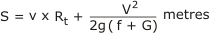 |
|
This is the sum of the distance travelled during reaction time and during deceleration.
See following tables for typical distance values.
2.2 Timing
The time that the signals begin to flash is calculated so that a driver travelling at the posted speed limit, who passes the signals before they begin to flash, has sufficient time to clear the holding line at the traffic signals, railway crossing or other crossing / entering hazard prior to the traffic signals changing from green to yellow or the railway signals starting to flash or the hazard entering the conflict area.
| t = S + 22 seconds v |
where S = distance (as measured on site), (m) v = posted speed limit, (m/s) t = time the signal begins to flash (sec) |
The constant of 22m (based on Canadian Standards) is added to account for the probability that the flashing signals may be out of direct vision at close range even though the signal has not been passed; i.e. the signal can start flashing when the vehicle signal is within 22m of the signal and the driver may not see them.
The signals, once activated, shall remain flashing for the duration of the red control signal, flashing red railway crossing signal or presence of the crossing hazard. The signals shall flash alternately at a frequency of 1 Hz.
See following tables for typical timing values.
TABLE 1 : Advance Warning Flashing Sign Location and Timing
Reaction / perception time = 2.0 second
Use for: Traffic Signals with 70km/h approach speed
|
|
GRADE |
|||||||||
|
SPEED |
-12% |
-9% |
-6% |
-3% |
0% |
3% |
6% |
9% |
12% |
|
|
|
|
|
|
|
|
|
|
|
|
|
|
70 |
Distance |
152 |
135 |
123 |
113 |
105 |
99 |
94 |
90 |
86 |
|
Time |
9.0 |
8.0 |
7.5 |
7.0 |
6.5 |
6.0 |
6.0 |
6.0 |
5.5 |
|
distance rounded to nearest metre; time rounded to nearest 1/2 second
TABLE 2 : Advance Warning Flashing Sign Location and Timing
Reaction / perception time = 2.0 second
Use for: Railway Crossings or other crossing hazards with 70km/h approach speed or Traffic Signals with 80km/h (or above) approach speed
|
|
GRADE |
|||||||||
|
SPEED |
-12% |
-9% |
-6% |
-3% |
0% |
3% |
6% |
9% |
12% |
|
|
|
||||||||||
|
70 |
Distance |
193 |
170 |
154 |
141 |
131 |
123 |
116 |
111 |
106 |
|
Time |
9.5 |
8.5 |
8.0 |
7.5 |
7.0 |
6.5 |
6.5 |
6.0 |
6.0 |
|
distance rounded to nearest metre; time rounded to nearest 1/2 second
TABLE 3 : Advance Warning Flashing Sign Location and Timing
Reaction / perception time = 2.5 second
Use for: Railway Crossings or other crossing hazards with 80km/h (or above) approach speed
|
|
GRADE |
|||||||||
|
SPEED |
-12% |
-9% |
-6% |
-3% |
0% |
3% |
6% |
9% |
12% |
|
|
|
||||||||||
|
80 |
Distance |
204 |
182 |
165 |
152 |
142 |
134 |
128 |
122 |
117 |
|
Time |
10.0 |
9.0 |
8.5 |
8.0 |
7.5 |
7.0 |
6.5 |
6.5 |
6.5 |
|
|
|
||||||||||
|
90 |
Distance |
250 |
222 |
201 |
185 |
172 |
162 |
154 |
146 |
140 |
|
Time |
11.0 |
10.0 |
9.0 |
8.5 |
8.0 |
7.5 |
7.0 |
6.5 |
6.5 |
|
|
|
||||||||||
|
100 |
Distance |
316 |
277 |
248 |
227 |
210 |
196 |
185 |
176 |
168 |
|
Time |
12.0 |
11.0 |
9.5 |
9.0 |
8.5 |
8.0 |
7.5 |
7.0 |
7.0 |
|
|
|
||||||||||
|
110 |
Distance |
417 |
357 |
315 |
284 |
260 |
241 |
225 |
212 |
202 |
|
Time |
14.5 |
12.5 |
11.0 |
10.0 |
9.0 |
8.5 |
8.0 |
7.5 |
7.5 |
|
distance rounded to nearest metre; time rounded to nearest 1/2 second
3. Design Presentation
Drawings and documentation shall be as detailed in Chapter 1 of this document.
In addition, the speed limit and gradients of the roads shall be shown on the drawings, as well as the speed limits of the rail where applicable.
4. Applicable Drawings
|
Traffic Control Signal Legends |
|
|
Traffic Signal Mast - 5.5m Outreach - General Arrangement & Details |
|
|
Advanced Warning Flashing Signs - Typical Electrical Construction |
|
|
Advanced Warning Flashing Signs - ELV Lamp Signal Lanterns - Wiring Details |
|
|
Advanced Warning Flashing Signs- LED Signal Lanterns - Wiring Details |
|
|
Advanced Warning Flashing Signs - At General Hazards - Typical Layout |
|
|
Advanced Warning Flashing Signs - At Rail Crossings - Typical Layout |
|
|
Advanced Warning Flashing Signs - School Crossings Signal Layout |
200431-0108 |
|
Advanced Warning Flashing Signals at School Crossings and Signs at Isolated Hazards - Schematic Circuit |
200431-0109 |
|
Advanced Warning Flashing Signals at School Crossings and Signs at Isolated Hazards - Controller Panel Layout |
200431-0110 |
|
Advanced Warning Flashing Signals at School Crossings and Signs at Isolated Hazards - Switchboard Details |
|
|
Traffic Control Signals - Traffic Signal Faults – Controller Label |
|
|
Traffic Control Signals - Double Lid Cable Pit & Termination Pit - Typical Details |
|
|
Traffic Control Signals - Controller Base Moulding |
|
|
Traffic Control Signals - 29 Core Termination Box - Detail Drawing |
|
|
Traffic Control Signals - 51 Core Termination Box - Detail drawing |
|
|
Traffic Control Signals - Typical Conduit Layout - For Future Signal Installation |
|
|
Traffic Control Signals - Conduit, Pit, Post & Loop Layout - Typical 4-Way Intersection |
|
|
Traffic Control Signals - Conduit Layout |
|
|
Traffic Control Signals - Conduit layout - Typical T Intersection |
5. Example Charts and Diagrams
See Main Roads Western Australia Specification 711.