Design of Kerbing
Table of Contents
1. General
This guide outlines Main Roads approach to the design of kerbing so that consistent approach in the design of kerbing is applied throughout Western Australia.
The guideline has been developed to be read as a supplement to the Main Roads Supplement to Austroads GRD Part 3: Geometric Design". The Main Roads Guide contains additional requirements, clarifications or practices that are different from the Austroads documents.
2. Introduction
Kerbed roads have a significant effect on driver behaviour. Kerbing affects the distance that drivers align their vehicles from the edge of a road and acts as a physical and psychological barrier that discourages them from leaving the road surface. Generally lateral placement of vehicles varies with kerb height and steepness as well as the location of other obstructions outside the kerb-line. Kerbing improves delineation of road edges and contributes to the appearance and safety of the road.
The main purposes for kerb construction are:
- To assist drainage.
- To improve channelisation and delineation of traffic flows.
- To protect pedestrians.
- Improvement of aesthetic values of the road alignment.
- To reduce maintenance of shoulders.
- To provide a boundary to landscaping treatments.
The use of kerbing to control vehicle movements is generally recommended in urban environments particularly at intersections because it is most effective at low speeds and small angles of impact. Kerbing is not recommended on rural roads and on high-speed roads, unless specifically required to improve channelisation at rural intersections, to control drainage in cuts, on bridges etc.
Construction of kerbing may significantly affect the cost of a project. Therefore, construction of kerbing should be justified in the following situations:
- Limited road reserve (introduction of kerbing reduces the cross-section width).
- Deep cuttings (to assist drainage).
- Special environmental requirements (control accidental spills, drainage of bridges etc.).
- Structural requirements (to protect high embankments from scouring)
3. Type of Kerbing
The two basic classes of kerbs are barrier and mountable kerbs. Each class has different types including semi-mountable and semi-barrier kerbs with a variety of designs (Figure 1). Dimensions of the most common types of kerbing used on Western Australian roads are detailed in Drawing No 9331-0376.
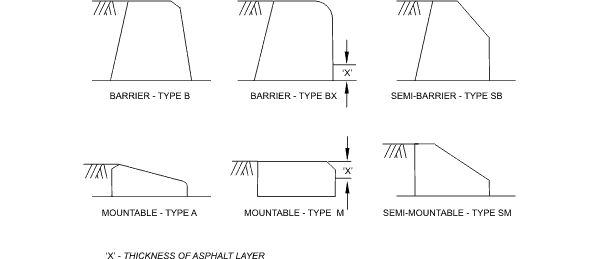
Figure 1 - Type of Kerbs
3.1 Barrier Kerb
Barrier kerbs are steep-faced and are designed to prevent vehicle encroachment on the roadside. Their main functions are:
- to discourage vehicles from using areas outside the travelled way, not intended for vehicular travel;
- to control drainage;
- to control parking of vehicles;
- to reduce the risk to pedestrians.
The typical barrier kerb is 150mm high. This height is effective to prevent vehicle encroachment into the roadside at low to moderate speeds.
Barrier and semi-barrier kerbing should generally be avoided on freeways or highways with design speeds of over 70 km/h because impact with kerbing on high-speed roads may overturn a vehicle or result in a vehicle becoming airborne.
Barrier-type kerbs may be used on sections of road where separation of opposing traffic is essential due to the high safety risks associated with traffic volumes, percentage of heavy vehicles, speed, crash history etc.
If a design allows for kerbed shoulders with barrier type kerbing the shoulder width should be adequate to accommodate a disabled vehicle (eg. AASHTO recommends a min of 1.8m; Austroads recommends a minimum width of 2.0m). The desirable shoulder widths for rural and outer urban roads are shown in Main Roads Supplement to Austroads GRD Part 3: Geometric Design – Table 4.3.
Barrier kerb, if positioned along the edge of a traffic lane, gives drivers a sense of restriction. Also large vehicles travelling along kerbed carriageways have no additional space in which to manoeuvre or to allow for sway of the rear trailer. It is recommended to avoid this type of kerbing on roads with restricted lane width and high percentage of heavy vehicles.
Barrier kerbs reduce the risk to pedestrians, not only as a physical but psychological barrier as well, because drivers generally tend to shy away from the kerb line. For this reason, barrier kerbing is recommended in built-up areas adjacent to footpaths with considerable pedestrian traffic, shared use paths and also at bus bays.
Barrier-type kerb may be used on low speed (< 70 km/h) arterial roads in order to prevent mid-block turns.
Some of the above text was adopted from AASHTO's Policy on Geometric Design of Highways and Streets (2004).
3.2 Semi-barrier
This type of kerbing is recommended where pedestrian traffic is light and a barrier type could tend to reduce traffic capacity due to the impression of restriction.
3.3 Mountable
Mountable kerbs (Type A and M) are generally used in the following situations:
- At the outer mountable island area of intersections, small corner islands and roundabouts to outline standard vehicle travelled paths.
- To define the left edge of a through carriageway where the crossfall of the adjacent shoulder or parking strip is opposite to that of the through carriageway.
- Where crossing or encroachment by vehicles larger than the design vehicles is permitted (e.g. at roundabouts) or expected under emergency conditions.
-
In front of road safety barriers.
-
On pedestrian and cycle paths along the grassed edge of asphalt paths to reduce damage to the path from the grass growing into the asphalt path. Kerbing along paths also provides visual contrast to the path edge and prevents the verge material erosion onto the path.
- Mountable Type A-D is specifically used for driveway.
Flush type kerb (refer to Type M in Figure 1) are generally used in the following situations:
- On lightly travelled residential streets because it does not require modification at driveway entrances.
The design of mountable kerbs should not result in loss of vehicle control or undercarriage damage when struck.
3.4 Semi-mountable
Semi-mountable kerbing should be used at all intersections, junctions and island treatments and is often used on outer separators and raised medians on bridges.
Semi-mountable kerb may also be used along pedestrian and cycle paths.
3.5 Other
The following types of kerbs are used to enhance the visibility/perception of a road alignment:
- High-visibility kerbing may be specified by a designer in areas where visibility is restricted due to fog or extended rains. For this purpose white marking or white cement may be used as per AS 1742.2 - 1994.
- Reflective kerbs use retro-reflective markings to improve visibility/perception. They are advantageous at night if placed along through-lane edges and island kerbs at intersections with high percentage of night-time crashes.
- Where such alternative kerb types are proposed to be used on roads managed by Main Roads, approval from the Main Roads Project Manager shall be obtained.
3.6 Kerb and Channel
Kerb and channel treatment is currently not used by Main Roads WA.
3.7 Kerb Key
Kerb key can be used at area which is subject to heavy vehicle impact, with approval from MRWA Asset Management.
4. Manufacturing and Placement
Specifications for placement and manufacture of concrete kerbs are defined in AS 2876-1987 and Main Roads Specification 407 - Kerbing.
5. Kerb Transitions
Transition from different kerb types, treatment of kerb introduction and surfaces is shown on the Main Roads' Drawing No 9331-0377.
6. Position of Kerbs
Main Roads preferred plan layout details of kerbing and approach offsets are detailed below and are shown on Main Roads Drawing No. 200231-0053.
Approach Offsets: Approach offset to kerbs is directly related to speed. Standard practice is to increase the offset distance from the edge of the adjacent traffic lane by 0.2m per 10km/h of design speed, although lateral placement of vehicles also varies with kerb height and steepness as well as the location of other obstructions outside the kerb-line.
Traffic Islands: All kerbed islands within channelisation should be set back from the edge of the through lane as shown on Drawing No. 200231-0053.
Separate Turning Lanes: Kerb approach offsets to left/right turn lanes may be reduced to 0.6m if the kerb starts after the turning lane taper. Typical detail is shown on Main Roads Drawing No. 200231-0053. For other situations kerbing should be placed as described in Approach Offsets above.
Median Kerbing: If barrier kerbs are used for median delineation, an offset of at least 0.3m (0.6m preferable) should be provided. If barrier type kerbs are introduced irregularly along streets the offset from the edge of travelled way should consistently be a minimum of 0.6m. This minimum may be used to match local authority standards on roads with design speed of 70km/h or less.
Median Openings: Median openings should generally not be kerbed except when the median between openings is kerbed.
Kerbs on Bridges: Median kerbs on single carriageway bridges should be of the same type and in the same location as on the adjacent roadways.
Kerbs along Safety Barriers: Kerbs are not desirable in front of safety barriers because they can cause unpredictable post-impact trajectories. For details on kerb placement adjacent to safety barriers refer to Main Roads Supplement to Austroads GRD Part 6: Roadside Design, Safety and Barriers.
Kerbs along Shoulders: Kerb may be placed on the outer edge of shoulder to control drainage, improve delineation and reduce erosion.
On low speed roads (< 70km/h) in restricted urban environment, mountable or semi mountable kerbs may be placed at the edge of a through lane to enhance delineation, although it is preferable that at least 0.3m offset to the kerbs is provided.
Kerbing adjacent to On-road Bicycle Lanes: Kerbing should be placed in accordance with Figures 4.6 & 4.7 Austroads GRD Part 6A: Pedestrian and Cyclist Paths.
Kerbing on Pedestrian and Cycle Paths: Depending on drainage requirements both mountable and semi-mountable kerb may be used along the edge of the path.
Kerbs at Intersections Where Kerbing is only Developed at the Intersection: On the approach side of an intersection where turning pockets are introduced, the kerb should follow the tangent line of the turning pocket. This is shown on Main Roads Drawing No. 200231-0053.
On the exit side, the kerb should finish 10m beyond the tangent point to assist in visual perception of the oncoming straight (uniform) section of the alignment. The median kerb should also finish opposite this point, if it is within a reasonable distance of the median kerb tangent point (<10m).
Kerbing along High Embankments: In some circumstances kerbing can be used to control stormwater runoff from the road. For example, on high embankments in order to prevent scouring of the batter and in deep cuttings where the road is below the water table. In these situations the kerb is placed at the back of the sealed shoulder.
7. References
A Policy on Geometric Design of Highways and Streets - AASHTO (2004)- Main Roads Supplement to Austroads GRD Part 6: Roadside Design, Safety and Barriers.
- AS 2876 - 2000 - Concrete Kerbs and Channels (gutters) - Manually or Machine Placed.
- Austroads GRD Part 6A: Pedestrian and Cyclist Paths.
- Pedestrians and Cyclists Facilities - MRWA.
- Main Roads Supplement to Austroads GRD Part 3: Geometric Design.
- AS 1742.2 - 1994 -Manual for Uniform Traffic Control Devices - Traffic Control Devices for General Use