Waterways Investigation Guideline
Table of Contents
1. General
This document shall be used as a guideline to achieve the MINIMUM survey requirements necessary for the collection of suitable field data for waterway analysis.
It must be understood, waterway analysis is site specific and it is unrealistic to expect a generic guideline that will accommodate each and every individual scenario.Therefore, this guideline provides the minimum requirements for Waterway Investigation Surveys. Prior to the commencement of the survey, consultation with the Main Roads Waterway Section will be required for guidance on additional site-specific requirements.
This guideline shall apply to all watercourses considered large enough to warrant the installation of a major waterway structure.
2. Guideline for Waterway Investigation Surveys
2.1 Introduction
The geometric characteristics captured in the field are used to determine hydraulic aspects such as stage/discharge relationships, velocity/discharge relationships, and peak flow analysis.
Waterway Investigation Surveys are performed to capture and model the physical geometric characteristics of a waterway (open flow channel) for use in the hydraulic analysis of a waterway and subsequent design of appropriate waterway structures e.g. bridges, culverts and flood-ways.
2.2 Survey Requirements
A full detail survey of the study area will be required and such detail shall be captured in accordance with Main Roads Western Australia Survey and Mapping Standard 67-08-43 "Digital Ground Surveys".
2.3 Survey Datum
Unless otherwise directed by the Main Roads Western Australia Waterway Section, all Waterway Investigation Surveys shall be supplied in the applicable Mainroads approved project zone for that location. These grids are available from the Mainroads Senior Geodetic Surveyor or online at
http://ims.mainroads.wa.gov.au/surveyportal/
All project zones are based on the Geocentric Datum of Australia 1994 (GDA94) and Australian Height Datum (AHD) unless otherwise specified.
2.4 Survey control
2.4.1 Horizontal Survey Control
Most large waterway surveys will require a minimum of three (3) Road Reference Marks (RRMs) to form the basis of the Waterway Investigation Survey.
This is to ensure that future survey work can be completed using the same datums and that check measurements can be made, regardless of instrumentation.
New survey control for Waterway Investigation Surveys shall be established, surveyed and lodged in accordance with the Survey and Mapping Standard 67-08-36 Road Reference Marks.
2.4.2 Vertical Survey Control
When a waterway survey is undertaken more than 10km from an established Benchmark or Road Reference Mark with Spirit levelled height value, it will be necessary to establish height on the new RRMs using GPS methodology.
It will however still be necessary to 3rd Order Spirit level between the newly established RRMs on site and indicate this on the control summaries and Metadata statement.
This statement will summarise the method used to establish the height and the expected absolute and relative accuracies obtained for the control.
2.4.3 Remote Areas
In very remote areas where AHD or GDA 94 control does not exist, a local datum may be used with an approximate GPS position for locating any control marks placed.
The intention for any control placed is that a high order of local network accuracy will still exist, from which designs can be determined and structures setout.
2.5 Detail Survey
In addition to the detail survey (refer to item 2.2) of the defined site, the following minimum additional waterways information shall be obtained at each site to assist the hydraulic analysis of the open channel flow.
2.5.1 Stream Profile (Hydraulic Gradient)
Enough levels and their positions must be observed so that the hydraulic gradient of the stream can be determined. Flowing water levels or reliable debris marks (refer 2.5.7 Flood Levels) should be obtained. If running water levels are observed, care must be taken to ensure the water body is truly flowing and not static or in areas of accumulated debris.
In the absence of running water levels or reliable debris marks,the gradient will need to be estimated from the slope of the streambed. Thus the levels observed shall follow the deepest flow of the watercourse or 'thalweg' rather than in an arbitrary straight line along the creek. The objective is to capture a true representation of the streambed gradient. Therefore, care must be taken to ensure the streambed profile is captured over a relatively long section to avoid the influence of localised scouring and sediment transport effects near existing waterway structures.
As a minimum, the stream profile shall extend 200 metres upstream and 200 metres downstream of the proposed crossing and/or existing structure.
2.5.2 Existing Roadways/Structures
If there is an existing road, the road centreline and adjacent natural surface (top and bottom of embankments, shoulders, sealed edges etc) are to be captured for the width of the flood plain and extending 150 metres beyond each side of the floodway or streambed.
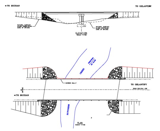
If the existing waterway structure is a bridge, a cross section is to be observed immediately beneath the structure along the approximate bridge centreline to enable the computation of the cross-sectional area enveloped between the underside of the bridge (soffit) and the channel bed. The position and shape of the existing bridge abutments, piers and soffits are to be captured and displayed to scale on the cross section plots to enable the computation/modelling of the affects the piers have on backwater, scouring and sediment deposition.

Figure 1:Typical required detail of existing structure and long section.
If the existing waterway structure is a culvert then the invert levels, culvert dimensions, shape and diameter, full road pavement width, headwall or stone pitching, and culvert material eg. reinforced concrete (RCP), shall be recorded.
2.5.3 Waterway Cross Sections
The objective of observing waterway cross-sections is to best define the waterway channel configuration for use in estimating the true cross-sectional area of flow.
Care must be taken when choosing the location of the cross sections, to avoid areas influenced by localised backwater scouring and sediment transport effects.
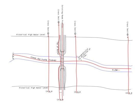
The cross-sections are to be observed perpendicular to the direction of flow and shall extend beyond the flood plain. The following cross sections shall be captured to best define the average streambed configuration:
- Within 30 to 50 metres upstream of the existing structure and/or proposed waterway crossing where the natural stream bed geometry is best represented.
- Along the approximate centreline of the proposed waterway crossing within the floodplain area. If this is not known at the time of survey then a cross section alongside the upstream edge of the existing structure may be requested.
- Within 30 to 50 metres downstream of the existing structure and/or proposed waterway crossing, where the natural stream bed geometry is best represented.
- If there is an existing bridge then an additional cross section shall be observed at least four (4) bridge lengths downstream from the bridge centreline.
- Additional cross sections shall be observed at any considerable variations in the streambed configuration or where the streambed is most restricted.

Figure 2: Minimum cross-section requirements for a perpendicular crossing for a uniform channel flowing perpendicular to an existing structure.
2.5.4 Skewed Cross Sections
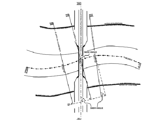
Where stream crossings are more complex, additional advice will be provided by the Main Roads Project Manager or the Waterways Section to survey more cross sections in order to provide a more accurate representation of the channel configuration.
If the section of waterway is skewed to the proposed alignment crossing and/or existing structure then the skew angle relative to the direction of flow must be measured and indicated on the plan.

Figure 3: Minimum cross sectional requirements for a skewed crossing.
2.5.5 Contour Plan
When the Survey Request includes the need for a 0.5 m interval contour plan, sufficient observations shall be taken to ensure compliance with the interpolated surface accuracy tolerance for natural surfaces as defined in the MRWA Survey and Mapping Standard 67-08-43 "Digital Ground Survey".
The required coverage shall extend at least 100 m upstream and downstream and 50 m beyond the flood plain i.e. beyond the highest water level either side of the waterway.
For large waterways the contour plan of the area can be obtained using photogrammetry to class C or better as specified in the Main Roads Survey and Mapping Standard 67-08-44 Mapping Standard.
If photogrammetry is used, the profile and cross-sections described above will still need to be carried out by field survey to obtain the required accuracy.
2.5.6 Existing Buildings and Services
Existing buildings provide a historical benchmark or datum for flood levels and photography. In the absence of survey measurement, flood levels in the past were often related to existing buildings for reference. By observing floor levels, we are able to relate many years of historical flood data and photography to the present.
A waterway structure can have a significant general and local affect on the behaviour and hydraulics of river systems. The development of crossings and the restrictions of river sections may have a significant effect on the water level in the vicinity of the bridge. By observing the levels of buildings, services and structures in the general area, allowances can be made during the design phase to minimise the threats of flood damage as a result of the raised water levels.
Floor levels on all buildings, structures and all services such as pipes, power line, etc. within 500 metres of the waterway shall be surveyed and indicated on the plan plot.
2.5.7 Flood Levels
Flood levels upstream and downstream from crossings provide a basis for estimating gradient, discharge through structures, stage height and backwater, which provides an indication of the adequacy of existing waterways. The difference in water surface elevation between the upstream and downstream side of the bridge approach embankments is not the backwater produced by the bridge. The maximum backwater is some distance upstream of the structure and normal stage is not re-established until some considerable distance downstream.
Thus the survey requirement is for upstream flood levels to be taken at least a bridge length away from the bridge opening and downstream levels at least 4 bridge lengths downstream of the bridge. When selecting flood levels it is best to select the light type of debris such as grass and leaves or "dag lines" at each edge of the flood plain. Avoid selecting large heavy pieces of debris or debris deposited in thin shrubs that bend with the flow.
When collecting flood level data it is important to provide notes and take photographs of flood debris and other relevant features, which may assist the final analysis. The availability of such data enables hydrological investigations and designs to be performed with a greater level of confidence than if design flood estimates were based on theoretical estimates alone.
Estimates of hydraulic slope can generally be obtained from measurements of water levels of a stream in flood or from debris levels after the event. If digital photography is recorded, it is important to record the dates and times at which photographs were taken.
All flood levels shall be Surveyed in accordance with Main Roads Western Australia Survey and Mapping Standard ![]() 67-08-43 "Digital Ground Survey"and detailed on the site plan presentation.
67-08-43 "Digital Ground Survey"and detailed on the site plan presentation.
Flood levels and flow patterns can also be readily established by suitable aerial photography. Aerial photography can act as a guide for the surveyor to assist with the location and identification of flood levels in the field.
The Main Roads Western Australia Survey and Mapping guideline 67-08-99 "Aerial Photography" details the processes for accessing Landgate photographic archives.
Imagery may also be available from Internet providers such as "Google" but care must be taken as the date of imagery may be unknown.
2.5.8 Digital Photographs
Digital Photographs provide an accurate record of vegetation types, flood levels, debris lines and general topography at each site. As a minimum, photographs shall be taken:
- Looking upstream and down stream of the proposed crossing and/or existing structure, and
- In both directions along the centreline of the proposed crossing and/or existing structure, and
- In both directions along the observed channel cross sections.
- Of all suspected debris lines and flood levels.
- Of any evidence of scouring, flood damage, or sediment deposition.
- Of existing structures looking both upsteam and downstream to be taken from within 50 metres of the structure.
It is important that the locations and orientations of all photographs be clearly indicated on the lodged plans. Digital photographs shall be supplied in a software/format compatible with Microsoft Windows XP i.e. Word, Excel, and PowerPoint etc. They may be .jpeg; .tiff; or .ecw format
2.5.9 Local Knowledge
Any available flood information such as localised rainfall figures, storm durations and flood heights, duration and frequency of road flooding etc., obtained from local residents and regular road users can greatly assist final peak analysis. Such information if gathered is to be detailed in the final report together with contact details of the information source.
2.5.10 Report
A detailed report will be required to show how the survey outcomes were achieved
and is to include at least the following:
- Summary of how the control network was established and adjustment results
- Any site specifics that may effect the Waterway design
- Any onsite difficulties or reasons to change the requested outcomes
- List of any contacts made regarding site flood history
- Digital photographs
2.6 Supplied Information To The Consultant
The following information, shall be supplied by Main Roads Western Australia for the Consultant to assist with the planning of the waterway investigation survey requirements:
- Description and location of the work.
- A location plan with the defined area of survey.
- Any other relevant plans, or sketches
- Copies of existing Main Roads or Landgate Control Point summaries relevant to the survey.
- Definition of any specific data requirements not covered by sections 2.5.
- Referral to legal, safety, environmental or other requirements.
- Main Roads Project Zone name and zone parameters.
- Aerial Photography (if available).
- Digital Mapping of site(if available)
2.7 Information to be Lodged with Main Roads Western Australia
On completion of the Waterway Investigation Survey the Consultant shall lodge the following information with the nominated Main Roads Project Manager who in turn shall archive all the information with the Main Roads Road and Traffic Engineering Data Manager:
- A Quality Statement in accordance with Specification 67-08-46 "Quality Statement"
- Hardcopy Plan Presentation plot
- Hardcopy Long section profile plot
- Hardcopy Cross Section Plots
- Excel spreadsheet of observations showing chainages and elevations at 10m intervals for each profile and cross section.
- Digital copies of all Plots in Microstation or AutoCAD format.
- Digital Survey Data in accordance with the digital data lodgement requirements of the Survey and Mapping Standard 67-08-43 Digital Ground Survey.
- Information of all Control used in the survey project area.
- New control point information in accordance with the Survey and Mapping Standard67-08-36 Road Reference Marks.
- All supplied information as defined in section 2.6.
- Digital photographs
- Report may include items 1,5,8,9,11 above.
2.8 Plan Presentation
Plans shall be produced as per the examples provided with the survey brief and this guideline. All plans shall be checked and signed before being forwarded to the client. Example of Waterways Plan Drawing
2.9 Data Format
Main Roads uses the following software for all survey, design/drawing applications
- Road Design - MX
- Survey, Mapping and Geodetic- MX, SMIGS, MicrostationV8 and 12D
- Drawing production AutoCAD and Microstation-latest versions
All digital information lodged, shall be compatible with the above software.
All reports and documents shall be Microsoft Office XP compatible.
MX GenIO format: In accordance with Appendix B of the Survey and Mapping Standard 67-08-43 Digital Ground Survey
Digital Data can be presented on any of the following mediums:
- CDs
- CD-R (CD+R not accepted)
-700MB
-Windows XP compatible
and / or
- DVDs
-DVD-R (DVD+R not accepted)
-4.7GB
-Windows XP compatible
Note: data may be supplied in compressed files provided the supplied file is self extracting, and extraction details are provided.
3. References
The following documents relate to this Guideline:
Survey and Mapping Standard 67-08-43 "Digital Ground Survey"
Survey and Mapping Standard 67-08-36 "Road Reference Marks"
Survey and Mapping Standard 67-08-46 "Quality Statement"
Survey and Mapping Standard 67-08-44 "Digital Photogrammetric Mapping"
Survey and Mapping Standard 67-08-15 "Operational Requirements For Real-Time Kinematic (RTK) Global Positioning System (GPS) Surveying"
"Waterway Design A Guide To The Hydraulic Design Of Bridges, Culverts and Flood ways" AUSTROADS 1994.
4. Definitions
The following terms used in this procedure have the specific meanings indicated:
AHD - Australian Height Datum
DGS - Digital Ground Survey
SSM - Standard Survey Mark
RRM - Road Reference Mark
MCP - Minor Control Point
GPS - Global Positioning System
GDA - Geodetic Datum Australia
MGA - Map Grid Australia
MX - Design software package-Formerly known as MOSS Software
SLK - Straight Line Kilometres
DTM - Digital Terrain Model
Thalweg - Deepest flow of the Watercourse.
RTK - Real Time Kinematic-GPS observation method